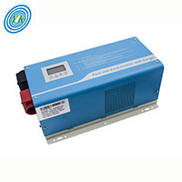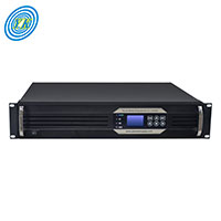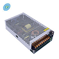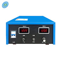
Advancing Power Solutions: The Comprehensive Guide to Low-Frequency Inverters with Chargers
Click: 876 Date: 01/18/2024 2::38::51 PM
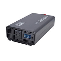
Advancing Power Solutions: The Comprehensive Guide to Low-Frequency Inverters with ChargersThe advancement of low-frequency inverters paired with chargers has led to a pivotal enhancement in energy storage systems, particularly within the realm of renewable energy sources like solar power. These systems, which convert direct current (DC) from solar panels or batteries into alternating current (AC) for use in homes and businesses, have become integral in the quest for sustainable and efficient energy utilization.The significance of battery efficiency in such inverters cannot be understated. Low-frequency inverters are advantageous due to their extended power cycles, which facilitate improved power management and utilization. By operating at lower frequencies, these inverters can generate AC power with minimal electrical noise and harmonics, thereby offering a more stable and cleaner power output suitable for sensitive electronic devices. This characteristic not only protects the devices but also ensures their efficient operation.Rack-mounted designs of solar hybrid inverters exemplify space optimization within energy storage systems. These inverters can be seamlessly integrated with existing solar power setups, promoting a more compact and maintainable energy solution. This integration is particularly beneficial as it can lead to reduced installation costs and simplified maintenance procedures.Furthermore, employing low-frequency inverters with chargers in solar energy systems can lead to significant cost savings. By optimizing the conversion efficiency from DC to AC, these systems reduce energy wastage, which in turn lowers electricity bills and accelerates the return on investment for solar power system owners. The clean energy produced by these systems also contributes to environmental sustainability by minimizing the carbon footprint associated with traditional electricity generation.The intersection of low-frequency inverter technology and energy storage marks a transformative period in renewable energy management. It underscores the importance of efficient energy conversion and storage, promoting energy independence and environmental stewardship. As the global community continues to embrace solar power, the role of such inverters in maximizing solar energy efficiency becomes increasingly vital, promising a greener and more sustainable future.Low-frequency inverters with chargers are crucial components in various power systems, providing reliable AC power from DC sources. Their construction is designed to handle significant power loads and surges, making them indispensable in many applications. In an article titled "Designing for Durability: The Construction of Low-Frequency Inverters with Chargers," we would explore the following facets:The Robustness of Low-Frequency Inverters: The hallmark of low-frequency inverters is their robust construction, which often includes heavy-duty transformers with a large iron core. These transformers are capable of withstanding high surge loads, making them suitable for applications involving motors, pumps, and tools that require a substantial initial power surgeTransformer-Based vs. Electronic Switching: Unlike their high-frequency counterparts that rely on electronic switching, low-frequency inverters use powerful transformers. This difference in design translates to a more reliable and sturdy performance, especially under high power levels. This is because transformers are generally less prone to damage than MOSFETs (Metal Oxide Semiconductor Field-Effect Transistors) used in high-frequency invertersCooler Operations and Efficiency Concerns: The transistors in low-frequency inverters, typically Field Effect Transistors (FETs), operate at a slower switching frequency, which allows them to run cooler. However, this design also results in a heavier weight and lower efficiency when compared to high-frequency inverters, with low-frequency models generally converting power at an efficiency between 60%-70%Customization and Feature Integration: Low-frequency inverters are often designed to be feature-rich, allowing for the integration of additional external GFCI outlets, multiple DC voltage inputs, regulated dual output voltages, and chemistry-appropriate battery chargers. They also often include transfer relays for seamless transition between shore power and inverter powerConsiderations for Specific Applications: While low-frequency inverters excel in handling heavy loads and providing durability, they may not be ideal for all scenarios due to their larger size and weight. They are best suited for systems where size and weight are not major constraints and where the ability to handle significant power fluctuations is necessaryBy examining these aspects, the article would provide a comprehensive understanding of the design and construction principles that underpin the durability of low-frequency inverters with chargers, as well as their suitability for various applications.Harnessing Renewable Sources: Integrating Solar Panels with Low-Frequency Inverter SystemsThe integration of solar panels with low-frequency inverter systems is a critical component in the advancement of sustainable energy solutions. Low-frequency inverters play a pivotal role in converting the variable direct current (DC) output of solar panels into a consistent alternating current (AC) that can be utilized by electrical grids or for off-grid applications. This conversion is essential because the AC electricity is what our modern infrastructure and appliances are designed to use.The Role of Low-Frequency Inverters in Solar Energy ConversionInverters are the heart of solar energy systems, tasked with the crucial role of transforming the DC power produced by solar panels into AC power compatible with the electrical grid. This process involves rapidly alternating the direction of the DC input to create an AC output. The resulting AC power must have a clean sine wave form to match the grid's power and avoid damaging electrical equipment.Grid Services Provided by Solar InvertersModern inverters extend beyond mere conversion; they are equipped to provide various grid services. For instance, they can supply reactive power to help maintain voltage levels and keep the current and voltage in phase, which is essential for the efficient operation of the grid. Additionally, inverters can help stabilize the grid by responding to deviations in voltage or frequency, ensuring a balance in the power system's supply and demand.Grid-Forming Capabilities of Advanced InvertersAdvanced inverters, known as grid-forming inverters, take on additional responsibilities, such as initiating a black start to reboot the grid after a complete shutdown. Unlike conventional grid-following inverters that depend on the grid's signal, grid-forming inverters can autonomously generate the necessary signal to produce a sine wave, allowing for a stable grid in the absence of traditional turbine-based generation.Integration with Battery StorageThe combination of solar panels and battery storage systems requires sophisticated inverters capable of managing power flows effectively. These systems can operate independently from the grid, providing resilience during outages. Advanced inverters are essential for these hybrid systems, managing the direct charging of batteries and ensuring the seamless transition between solar generation and battery supply.Future of Inverter-Based GridsAs the grid evolves to include more renewable energy sources, the role of inverters becomes increasingly significant. Traditional power generation, characterized by the inertia of massive turbines, is gradually giving way to inverter-based generation, which lacks physical inertia but offers the flexibility to produce energy at any frequency. The transition to an inverter-based grid necessitates the development of smarter inverters that can adapt to and mitigate disruptions, contributing to a stable and reliable power supply.The integration of solar panels with low-frequency inverter systems is not only a technological advancement but also a step towards a cleaner, more sustainable future. By harnessing renewable sources and refining the capabilities of inverters, we can ensure a resilient and efficient energy grid for generations to come.When it comes to low-frequency inverters, one of the critical factors is their ability to handle surge capacities. These devices are designed to convert DC power from batteries or other sources into AC power, which can be used to run various electrical devices. Surge capacity is particularly important for starting inductive loads, such as motors found in refrigerators, pumps, and air conditioning units, which require a higher initial power burst when starting up.Low-frequency inverters are often preferred for heavy-duty applications because they are typically designed with robust transformers capable of handling high inrush currents associated with starting inductive loads. This contrasts with high-frequency inverters, which may struggle with these surge demands due to their reliance on electronic circuitry rather than heavy-duty transformers.A surge capacity challenge article could delve into the specifics of how low-frequency inverters manage these power demands. It could explain the role of transformers in these inverters and how they contribute to the inverter's ability to sustain surges. Moreover, the article could discuss the design considerations that go into making low-frequency inverters capable of handling high power levels, such as the choice of materials, transformer design, and the implementation of protective features to prevent damage during power surges.The article could also compare the performance of low-frequency inverters with their high-frequency counterparts, highlighting scenarios where one might be preferred over the other. For instance, while low-frequency inverters are excellent for surge capacity and reliability, they are also typically heavier and more expensive, which might not be ideal for all applications.Additionally, the article could provide insights into how users can optimize their systems for surge capacity by selecting the right size and type of inverter, considering the total power requirements, and understanding the startup characteristics of their appliances. It could also touch on the importance of a proper installation and maintenance routine to ensure the longevity and performance of the inverter.Lastly, the article could explore the future of low-frequency inverter technology, discussing potential improvements in materials and design that could enhance surge capacity while reducing size, weight, and cost. This could include advancements in semiconductor technology, transformer design, and energy storage solutions that complement the inverter's capabilities.In summary, an article titled "The Surge Capacity Challenge: Ensuring Peak Power in Low-Frequency Inverters" would provide a comprehensive overview of how low-frequency inverters handle surge capacity, the design principles behind these robust systems, practical advice for users, and a look into the future of inverter technology.Low-frequency inverters with chargers are a crucial component in the realm of power conversion and energy systems, catering to both residential and industrial applications. These inverters not only convert direct current (DC) from batteries or renewable sources into alternating current (AC) for use in electrical appliances, but they also feature built-in chargers to replenish battery power. This article explores the versatile applications of low-frequency inverters with chargers, highlighting their significance across various sectors.Residential Energy IndependenceIn residential settings, low-frequency inverters with chargers provide homeowners with a reliable source of power, especially in areas with unstable grid electricity. These inverters can draw energy from solar panels or wind turbines, store it in batteries, and then supply the household with AC power. The built-in charger ensures that batteries are recharged during low energy consumption periods, guaranteeing an uninterrupted power supply.Industrial Process OptimizationIndustries benefit from the precision and control offered by low-frequency inverters with chargers. They regulate the operation of heavy machinery, ensuring optimal performance and energy savings. For example, in manufacturing plants, these inverters adjust the speed and torque of motors to match production needs, reducing wear and tear on equipment and lowering energy costs.Emergency Backup Power SystemsCritical facilities such as hospitals and data centers rely on uninterrupted power to maintain operations. Low-frequency inverters with chargers form the backbone of emergency backup power systems, instantly providing power in case of a grid failure. The charger keeps the batteries ready to deliver power when needed, ensuring vital services remain operational.Renewable Energy IntegrationAs the world shifts towards sustainable energy solutions, low-frequency inverters with chargers play a pivotal role in integrating renewable energy sources into existing power systems. They handle the variable output from solar and wind installations, provide power conditioning, and enable energy storage for later use.Off-Grid Living and Remote ApplicationsFor remote locations where grid power is unavailable or unreliable, low-frequency inverters with chargers are essential. They empower off-grid living by providing AC power from renewable sources or generators. The charger component maintains battery health, ensuring a consistent power supply for homes, research stations, or remote telecommunication sites.In conclusion, low-frequency inverters with chargers are versatile and critical components that cater to a wide range of applications from residential to industrial use. They ensure energy efficiency, operational reliability, and the seamless integration of renewable energy sources, highlighting their importance in modern electrical infrastructure.

Click: 1049 Date: 01/17/2024 4::53::57 PM
Enhancing Performance and Safety in Isolated DC-DC Converters: From Industrial to Military ApplicationsGalvanic isolation in DC-DC converters is crucial for both safety and functional reasons, as it separates the input and output electrically, preventing dangerous high voltages from affecting the low voltage side. With advances in technology, galvanic isolation techniques have significantly improved, enhancing the performance and reliability of isolated DC-DC converters.1. Introduction to Galvanic Isolation in DC-DC ConvertersGalvanic isolation is the practice of physically and electrically separating the input and output sides of a DC-DC converter. This isolation is typically achieved using a transformer, ensuring no direct conduction path exists between the input and output. Isolation is essential for safety, noise reduction, and preventing ground loops.2. Technologies Enhancing Galvanic IsolationRecent technologies have introduced new materials and designs for transformers and optocouplers, which are commonly used for feedback in isolated converters. High-frequency transformers have become smaller and more efficient, while optocouplers have seen improvements in speed and reliability. Silicon carbide (SiC) and gallium nitride (GaN) semiconductors are now used in some isolated converters, offering better performance at high frequencies and temperatures.3. Improved Transformer Design and MaterialsTransformers in isolated DC-DC converters have seen advancements in core materials, which reduce losses and allow for operation at higher frequencies. This has led to smaller, more compact transformers that can fit into tighter spaces without sacrificing performance. New winding techniques have also been introduced to minimize leakage inductance and improve efficiency.4. Enhanced Isolation Techniques and StandardsIsolation techniques have improved to meet higher safety standards, such as reinforced insulation and increased working voltages. Regulatory standards like UL, IEC, and EN dictate the requirements for isolation in various applications, driving the development of more advanced isolation methods.5. Innovations in Isolated Converter TopologiesNew converter topologies have been developed to optimize the use of galvanic isolation. Advanced topologies such as the LLC resonant converter and active clamp forward converters offer higher efficiency and power density while maintaining isolation. These topologies are becoming more popular in applications that require high reliability and power conversion efficiency.Conclusion: The Future of Galvanic IsolationThe continued innovation in materials, technologies, and topologies is pushing the boundaries of galvanic isolation in DC-DC converters. These advancements are making isolated converters more efficient, compact, and suitable for a wider range of applications, from industrial to medical and aerospace. As electronic devices become more prevalent and power conversion needs evolve, the role of galvanic isolation will remain a critical factor in the design and operation of safe and efficient power systems.In the realm of power electronics, optimizing power efficiency is a critical aspect of designing switching converters. This article explores the methodologies and technologies instrumental in enhancing the power efficiency of switching converters.Understanding the Thermal Challenges and Integration in Switching Converters Switching converters, which include components like controllers, converters, and modules, are subject to thermal challenges as they dissipate heat. Integration of components such as field-effect transistors (FETs) and inductors can lead to smaller sizes and ease of use, but also introduces thermal management issues. As integration increases, fewer options are available to improve efficiency, necessitating careful optimization of device operation at high ambient temperatures to minimize power loss.The Crucial Role of MOSFETs in Efficiency Power MOSFETs, which act as switches in DC/DC converters, have parameters like on-resistance (RDS(on)) and gate charge (QG) that significantly impact efficiency. To optimize efficiency, designers need to balance between RDS(on) and switching losses. The goal is to equalize switching losses with conduction losses, which can be achieved by selecting FETs with low RDS(on) and QG, and by sizing high-side and low-side FETs to equalize conduction losses.The Impact of Switching Frequency on Power Loss Switching frequency is a critical parameter that influences power loss in converters. Higher frequencies lead to increased switching losses, while lower frequencies result in larger inductors, which can have higher DC resistance and thus higher conduction losses. Finding an optimal switching frequency that balances these losses is key to improving efficiency.Optimizing Inductor Selection for Efficiency The power inductor, a core component of DC/DC converters, must be carefully selected to manage ripple current and minimize losses. The choice of inductor value and the trade-off between inductor size and switching frequency are essential considerations. Inductor core losses also depend on switching frequency and core material, with different materials offering varying performance at high frequencies.Control-Based Optimization Techniques Control-based optimization involves creating accurate mathematical models of converter operation to minimize losses. This approach involves precomputing optimal control patterns and implementing them online to improve efficiency and extend the operational range of the converter. Such optimization can lead to significant reductions in losses, especially during rapid changes in power references or during fast transients.Automated Optimization with Voltage Input-to-Output Control (VIOC) VIOC technology enables automated control of a switching converter's output voltage, optimizing the efficiency of a downstream LDO regulator. By reducing the voltage differential across the LDO regulator, VIOC decreases power dissipation and improves system efficiency. This technology is particularly beneficial for systems with variable loads, as it can adjust the output voltage of the switching converter to maintain a constant voltage drop across the LDO regulator.In conclusion, optimizing power efficiency in switching converters is a multifaceted challenge that requires careful consideration of thermal management, component selection, and control strategies. By leveraging advancements in control-based optimization and technologies like VIOC, designers can significantly enhance the efficiency and performance of their power conversion systems.Voltage regulation in isolated power systems is a critical aspect of ensuring stable and reliable power delivery to various electronic devices and systems. This article will discuss several techniques used to maintain a consistent output voltage despite variations in the input voltage or load conditions.1. Understanding the Minimum Controllable On-Time for High-Frequency Switching: When designing isolated power systems that operate at high switching frequencies, it is essential to consider the minimum controllable on-time of the power controller. The on-time, or the duration the power switch is conducting, can become a limiting factor when the input to output voltage ratio is very small. To address this, designers can either reduce the switching frequency or employ controllers designed to handle lower duty cycles.2. Utilizing External References for Low Output Voltage Regulation: In cases where the output voltage is significantly lower than the reference voltage of the controller, an external reference can be employed. By connecting an external reference with a higher voltage than the controller's internal reference to the feedback loop, the system can regulate to voltages below the internal reference. Choosing an accurate reference can significantly improve the precision of the output voltage.3. Biasing Techniques to Achieve Desired Voltage Outputs: Integrating an external reference requires a resistor to provide the necessary bias current. This setup allows the controller to 'trick' the system into regulating at voltages lower than its internal reference. This approach is beneficial when dealing with very low output voltages that are challenging to achieve with standard controllers.4. Addressing Accuracy Concerns in Voltage Regulation: The accuracy of the output voltage can be affected by the choice of the external reference. For applications where precision is paramount, it may be necessary to use a reference with 0.1% accuracy, although this may come at a higher cost compared to the more common 1% or 2% references. Some controllers offer auxiliary bias rails that might serve as an alternative to the external reference; however, these rails are usually less regulated and might not provide the desired accuracy.5. Selecting the Right Controller for Low-Voltage Applications: When the requirement is to regulate a very low output voltage, the selection of the controller becomes crucial. While controllers with a reference voltage lower than the required output voltage are rare, especially below 0.8V, certain techniques and additional components can be utilized to overcome these limitations and achieve the necessary regulation.In summary, this article explores the intricacies of voltage regulation in isolated power systems, particularly focusing on methods to manage low output voltages and the importance of choosing the correct components and techniques to maintain accurate and stable voltage levels.Electromagnetic interference (EMI) can significantly impact the performance and reliability of DC-DC converters in industrial applications. Implementing effective EMI filtering strategies is crucial for ensuring that these power conversion devices operate without disrupting or being affected by unwanted electrical noise. Here are some strategies for minimizing EMI in industrial DC-DC converter applications:Local Shielding of Converters: It's important to design PCBs with the possibility of adding local shields to mitigate EMI. Even with magnetically shielded inductors and good PCB design, EMI can still be a concern. One method is to incorporate "fencing solder strips" on the PCB, which can connect to the ground reference plane (GRP) and provide a means to add shields if necessaryStrategic Placement of Components: Keeping antennas and coaxial cables at a distance from DC-DC converter circuitry can reduce the risk of EMI coupling. Since converters can generate high electric fields, they can potentially interfere with nearby receiver equipment, affecting the performance of wireless communication modules.PCB Stack-up and Grounding: A well-thought-out PCB stack-up is essential. Signal layers should have an adjacent GRP to prevent noise and signal coupling. Power traces should also follow this rule to reduce radiated EMI and crosstalk. A solid GRP is crucial as gaps or slots can propagate EMI across the boardUse of Shielded Inductors: Opting for shielded inductors instead of unshielded ones can confine magnetic fields more effectively. Shielded inductors prevent the spread of the H-field, which is critical in minimizing EMIProper Orientation of Inductors: The orientation of inductors can influence EMI characteristics. Inductors have a start and an end to their windings. By connecting the start of the winding to the switched output of the converter IC, and the end to the output filter, EMI can be reduced since the start is somewhat shielded by the subsequent turnsConcentrated Converter Circuitry: Keeping all converter circuitry on the top layer of the PCB and not running fast switching signals through multiple layers can prevent EMI issues. Also, keeping converter components close to the IC can minimize the loop areas, which is crucial for reducing EMIThese strategies are derived from a combination of best practices in PCB design and specific techniques for mitigating EMI in DC-DC converters. By carefully designing the converter's physical layout and incorporating EMI-reducing components, industrial applications can achieve better performance and compliance with EMC standards.The field of military electronics is one that demands the utmost in reliability and performance, especially when it comes to power conversion technologies. High voltage DC-DC converters are a crucial component in this domain, as they provide the necessary power conversion capabilities for a wide range of defense-related applications.In recent developments, Gaïa Converter has introduced the MGDM-500 series, a 500-Watt DC-DC converter designed specifically for high-reliability aerospace and defense applications. This series represents a significant innovation in the power supply domain, offering engineers the flexibility to create power architectures that adhere to stringent military standards, such as MIL-STD-461/704/1275 and DO-160.The MGDM-500 series stands out for its ability to deliver a stable 500-Watt power output across a wide input voltage range, from 9 to 36 volts DC, with the capacity to handle transient input voltages up to 40 volts DC for brief periods of time. This robustness is complemented by high power density and efficiency, packaged in a compact half-brick format.Notably, the MGDM-500 series features galvanic isolation of 1,500 volts DC, which is critical for ensuring the safety and reliability of electrical systems by preventing ground loop issues and providing protection against voltage spikes. Additionally, the output voltage of these converters can be adjusted from 90 to 110 percent, allowing for greater control and customization to meet specific application requirements.Perhaps one of the most impressive aspects of the MGDM-500 series is its ability to operate without derating over a wide temperature range, from -40 to 105 degrees Celsius. This ensures that the converters can reliably function in the extreme environmental conditions often encountered in military settings.In summary, innovations like the MGDM-500 series from Gaïa Converter are pushing the boundaries of what's possible in high voltage DC-DC conversion for military use, offering high reliability, adaptable power output, and operation under extreme conditions. These advancements are critical for powering the next generation of military technology, where failure is not an option.
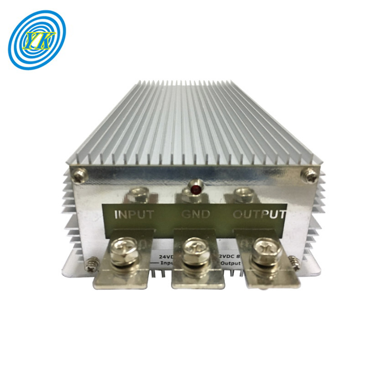
Essentials of Buck/Boost DC-DC Converters: From Basic Operation to Advanced Design
Click: 768 Date: 01/16/2024 2::02::49 PM
Essentials of Buck/Boost DC-DC Converters: From Basic Operation to Advanced DesignThe principles of voltage conversion techniques involve transforming electrical power from one form to another while maintaining control over various parameters to ensure efficiency and safety. The conversion process typically includes several key steps:Input Voltage and Frequency Adjustment: This involves modifying the input voltage and frequency to levels suitable for the system's circuitry. For instance, an input transformer can step down high AC line voltage to a more manageable low voltage level required by the system.Current Rectification: This step converts the adjusted AC voltage into DC voltage using input rectifiers.Voltage Smoothing: After rectification, the output typically contains ripples, which are smoothed out using capacitors to provide a steady DC level.Output Voltage Regulation: Voltage regulators ensure that the output voltage remains constant despite variations in line voltage, load, and temperature changes. This is crucial for maintaining the reliability and performance of electronic devices.Isolation: Electrical isolation between the input and output of the power supply is necessary for safety and noise reduction. This can be achieved through transformers or optocouplers.Efficiency and Power Density: Switching power supplies are favored in many applications due to their high efficiency and compact size. They use high-frequency switching techniques to control the energy transferred to the output.Output Ripple: The trade-off with switching supplies is typically a higher output ripple compared to linear supplies. However, this can be mitigated through additional filtering.Input Voltage Range: Switching power supplies can operate over a wide input voltage range without significantly affecting efficiency, making them versatile for various applications.Transient Response: These supplies may have slower transient response times compared to linear supplies but can provide better performance during voltage sags (brownouts).Power Factor Correction: To minimize energy loss in power distribution systems and meet utility requirements, power factor correction may be employed in the design of power supplies.Protection Features: Power supplies are designed with features to protect against overcurrent, overload, and short circuits to ensure safe operation under fault conditions.These principles are fundamental to the design and operation of power conversion devices like AC/DC power supplies, DC/DC converters, and DC/AC inverters. Each step in the conversion process is critical and requires careful consideration to achieve the desired performance and efficiency while ensuring the safety and reliability of the power supply.Efficiency and control in power regulation involve balancing the demands of delivering reliable power while optimizing the use of resources and maintaining costs. This topic can be explored through various angles:Maximizing Efficiency in Power Systems: This involves using technology and processes to ensure that power delivery is done with minimal waste and maximum utility. Techniques such as advanced metering infrastructure (AMI) and demand response help utilities to match supply with demand and reduce lossesControl Mechanisms in Power Distribution: Power regulation requires sophisticated control systems to manage the flow of electricity and maintain stability. Control mechanisms include automated switchgear, capacitor banks for reactive power management, and voltage regulators to ensure consistent service qualityCost Management and Economic Utilization: Effective power regulation requires strategies to control costs without compromising quality. This involves strategic investments in infrastructure, optimizing operational costs, and implementing energy-efficient technologiesAdapting to Technological Advancements: The power industry is continuously evolving with new technologies such as smart grids, renewable energy integration, and battery storage systems. Regulators must adapt policies and control mechanisms to embrace these changes while ensuring security and reliabilityRegulatory Framework and Policy Making: The regulatory environment plays a critical role in power regulation. It involves setting tariffs, ensuring fair competition, and promoting policies that support sustainability and innovation in the power sectorThese aspects are crucial for a stable, efficient, and cost-effective power regulation system that meets the needs of consumers and supports the growth of the energy sector.DC-DC Converters, particularly in Buck/Boost types, can be addressed by looking at various aspects of fault management and protection features in power electronics systems. Here are some key points that could be discussed under this heading:Fault Types and Diagnosis: Addressing the various types of faults that can occur in a power system, such as short circuits, overloads, and open circuits. Techniques for diagnosing these faults include monitoring current and voltage levels or using algorithms to detect irregular patterns indicative of a fault condition.Protection Mechanisms: Discussing the hardware and software mechanisms that are in place to protect against faults, such as fuses, circuit breakers, and solid-state protection devices. These mechanisms can isolate faults to prevent damage to other system components.Fault Response Actions: Outlining the typical responses to fault conditions, such as shutting down the converter, entering a safe mode, or switching to a redundant system to maintain operation despite a fault.Design for Reliability: Exploring design considerations that enhance the reliability of Buck/Boost converters, such as component derating, use of robust components, and thermal management to prevent overheating, which is a common cause of failure.Fault Tolerant Topologies: Presenting topologies for DC-DC converters that are inherently more tolerant to faults, including those that can reconfigure themselves to bypass damaged components or those that use redundancy to maintain operation after a fault.Monitoring and Telemetry: Discussing the importance of system monitoring and telemetry to provide real-time data on system performance. This data can be used for predictive maintenance and to quickly identify when and where a fault has occurred.Ground Rules and Requirements: Establishing a set of ground rules and requirements for fault protection design, ensuring that the system can maintain a safe state for a predetermined period following any anomaly, and that sufficient information is available for failure analysis and recovery actions.Autonomous Fault Protection: The implementation of autonomous fault protection to monitor, detect, and resolve faults as they occur, thereby preserving the overall health of the system and providing greater diagnostic capabilities.These points cover the spectrum of considerations and strategies involved in fault management and protection for power electronics systems like Buck/Boost DC-DC converters. They emphasize the importance of anticipating potential faults, designing systems to withstand them, and having robust mechanisms in place to deal with them when they occur.Buck-boost DC-DC converters play a critical role in energy storage systems by efficiently managing the voltage supplied to or from energy storage elements such as batteries, capacitors, or fuel cells. These converters adapt the voltage levels to match the specific requirements of the storage devices, ensuring optimal charging and discharging processes, as well as maximizing the lifespan and performance of the storage units.In renewable energy applications, such as solar or wind power systems, buck-boost converters help in stabilizing the fluctuating power output from these sources before it's stored or used. They ensure that the voltage levels are appropriate for charging batteries or for integration into the grid.In electric and hybrid vehicles, which rely on batteries for propulsion, buck-boost converters are essential for voltage regulation. They adjust the voltage levels to suit the needs of the vehicle's electrical system, enhancing the overall efficiency and reliability of the vehicle's power supply.In portable electronic devices, these converters optimize battery life by adjusting the voltage levels to the varying demands of the device. This ensures that the device operates effectively even as the battery voltage changes due to discharge.Moreover, in any DC microgrid scenario, buck-boost converters are pivotal in maintaining stable voltage levels for a variety of loads and sources, contributing to the overall resilience and efficiency of the microgrid system. They allow for seamless power flow between different voltage domains within the microgrid, facilitating the integration of diverse energy sources and storage solutions.When designing the layout for a switching regulator, such as a buck-boost DC-DC converter, there are several key considerations to ensure optimal performance and reliability. Here is a summary of the crucial design considerations:Grounding Strategy: Develop a solid grounding strategy to minimize noise and ensure stable operation. Segregate the analog and power grounds when possible, connecting them at a single point to prevent high-amplitude currents from the power section interfering with sensitive analog circuits .Component Placement: Place components strategically to minimize the loop areas of high-frequency current paths. Components with discontinuous current, like the switch node, should be placed close together to reduce stray inductance and associated EMI .Bypass Capacitors: Utilize high-frequency bypass capacitors on the supply pins of IC devices. Place these capacitors as close as possible to their respective pins and connect them to a clean, low-inductance ground .Trace Layout: Use wide traces for power paths to reduce resistance and improve efficiency. Keep high-current traces short to minimize inductance and reduce voltage spikes and ringing .Minimizing EMI: Be mindful of the placement and routing of components to reduce electromagnetic interference. This includes careful positioning of inductors and transformers to minimize radiated noise .Feedback Networks: Place voltage divider resistors used for feedback close to the feedback pin of the regulator to minimize noise coupling through capacitive effects .Thermal Management: Design the layout to accommodate heat dissipation, including the use of heatsinks or thermal vias if necessary, especially for components like power switches that may generate significant heat .Use of Layers: On multi-layer boards, consider using an inner layer as a shield to reduce interference and utilize multiple vias in parallel to lower resistance and inductance for power connections .Input and Output Capacitors: Place input and output capacitors close to their respective loops to contain high-frequency currents and minimize their interference with other parts of the circuit.By adhering to these guidelines, you can create a robust and efficient layout for a buck-boost switching regulator that will perform well across a range of operating conditions.

Exploring AC to DC Converters: Principles, Types, Applications, and Technological Advances
Click: 787 Date: 01/15/2024 3::01::52 PM
Exploring AC to DC Converters: Principles, Types, Applications, and Technological AdvancesThe fundamental principles of AC to DC conversion involve transforming the alternating current (AC) that is typically supplied to households and businesses into direct current (DC), which is used by a wide array of electronic devices. This transformation process is known as rectification and employs diodes, electronic components that permit current flow in one direction while blocking it in the opposite direction. Rectification comes in two primary forms: half-wave and full-wave. Half-wave rectification uses a single diode to pass only one polarity of the AC, resulting in a pulsating DC that only uses half of the input waveform. Full-wave rectification, on the other hand, utilizes four diodes in a bridge configuration to utilize the entire AC waveform, producing a smoother DC output with less ripple.After rectification, the output is not purely DC but contains AC components called ripples. To smoothen the DC output and reduce these ripples, a filtering stage, typically comprising a capacitor, is implemented. The capacitor charges when the rectified voltage rises and discharges when it falls, helping to maintain a more constant voltage.A regulation stage is often required to ensure that the output voltage remains stable despite fluctuations in the input voltage or changes in the load. Voltage regulators stabilize the output by compensating for these variations, maintaining a consistent DC supply necessary for the sensitive electronics that rely on it.These conversion processes are essential for the operation of a vast array of electronic devices and systems, from small gadgets to large-scale industrial machinery. Advances in converter technology continue to improve efficiency, minimize energy loss, and accommodate the compact form factors demanded by modern electronics.AC to DC converters are essential components in various electronic devices, converting alternating current (AC) from the electrical outlet into direct current (DC) required by many electronic circuits. Here are five categories of AC to DC converters:Single-Phase Rectifiers: These are the simplest type of AC to DC converters, commonly using diodes to convert the AC input to a pulsating DC voltage. They include half-wave rectifiers, which use a single diode, and full-wave rectifiers, which use multiple diodesBridge Rectifiers: A bridge rectifier uses four diodes in a bridge configuration to provide full-wave rectification. This type is widely used due to its ability to convert the entire AC wave to DC, making it more efficient than half-wave rectifiersSwitched-Mode Power Supplies (SMPS): These are more complex converters that include a switching regulator to convert electrical power efficiently. SMPS can be further divided into various types like buck converters (step-down), boost converters (step-up), and buck-boost converters (can do both)Power Factor Correction (PFC) Converters: These are used to improve the power factor of the system by aligning the phase of the input current with the input voltage, thereby increasing the efficiency of the power supply system. There are different topologies like bridge, semi-bridgeless, and bridgeless PFC convertersMulti-Stage Converters: These converters use more than one stage to accomplish the AC to DC conversion, which allows for better control, efficiency, and can include features like isolation and regulation. They can combine different types of converters to optimize performance for specific applicationsAC to DC converters are integral to a wide array of devices and systems, serving as the bridge between AC power sources and DC-powered electronics. Here are some applications where these converters play a crucial role:Consumer Electronics: AC to DC converters are fundamental in powering household gadgets such as laptops, smartphones, and tablets through their chargers. They are also found within the power supply units of televisions, audio systems, and other multimedia equipment.Industrial Machinery: In industrial settings, these converters are essential for operating machinery that requires DC power, ensuring smooth functioning of automation systems, motor drives, and control systems.Medical Equipment: Medical devices, including life-support machines, diagnostic instruments, and portable medical tools, rely on AC to DC conversion to ensure safe and reliable operation.Renewable Energy Systems: Converters are used in renewable energy applications such as solar power systems to convert variable AC from solar inverters to stable DC for storage or direct usage.Transportation Infrastructure: In the transportation sector, converters are used in electric vehicle charging stations, railway systems, and traffic control equipment to convert AC from the grid to the required DC voltage levels.These applications highlight the ubiquity and importance of AC to DC converters in both our daily lives and critical infrastructure.When designing AC to DC converters, it's crucial to consider several technical aspects that impact the converter's performance, longevity, and suitability for the intended application. Here are some key design considerations rephrased from the provided sources:Component Layout and Placement: The positioning of components on the PCB is essential. Strategically arrange components to minimize trace lengths, thereby reducing potential noise and electromagnetic interference. Ensure that parts that dissipate heat, like diodes and voltage regulators, have proper airflow or cooling mechanisms.Trace Dimensions and Grounding: The traces on the PCB must be wide enough to handle the expected current without excessive heating. Utilize a solid ground plane to establish a consistent low-impedance path for the return current, which aids in noise reduction.Heat Management: To manage heat effectively, components that generate significant heat should be placed in locations with good ventilation. Heat sinks, thermal vias, and other cooling techniques can be employed to help dissipate heat efficiently.Electromagnetic Interference (EMI) Considerations: Implement shielding strategies to minimize the impact of EMI on the circuit. This could involve adding conductive barriers or making use of grounded copper pours on the PCB.Component Selection: Choose components that are appropriate for the conversion process, such as rectifier diodes, capacitors for filtering ripple voltage, and transformers for stepping down the input voltage. The ratings of these components, such as voltage, current, and power, should align with the converter's requirements.Each of these considerations plays a critical role in the design and implementation of an effective and reliable AC to DC converter. By addressing these areas, designers can create converters that meet the necessary performance criteria while also being robust and efficient.Recent advancements in AC to DC conversion technology have been marked by significant strides in enhancing the efficiency and performance of power electronics and electric machines. These improvements are driven by the growing demand for electric vehicles (EVs), which require robust and efficient conversion systems to manage battery charging and energy distribution. The following points highlight some of the key areas of progress in converter technology:Innovative Electric Machine Designs: Efforts have been made to increase the power density and reduce the cost of electric motors, which are crucial for EV propulsion systems. Novel motor designs are being explored to achieve these goals, including the use of advanced materials and manufacturing techniques.Enhanced Inverter Technologies: Inverters, responsible for converting DC to AC, are seeing new topologies that improve efficiency and can handle higher temperatures while maintaining high reliability. These innovations are vital for managing the heat generated in high-power applications such as fast EV charging.Converter Efficiency Improvements: Converters are being designed to reduce the number of components and integrate multiple functions, leading to smaller, lighter, and more cost-effective solutions. This is particularly important for onboard chargers and power management systems in EVs.Thermal Management Solutions: As power densities increase, effective thermal control becomes more critical. Innovations in packaging technologies are being developed to improve heat dissipation, which is essential for the longevity and reliability of power electronics and electric machinery.Integrated Motor/Inverter Systems: The integration of motors and inverters into single units is an area of significant interest. Such integration can lead to reductions in size, weight, and cost, as well as improvements in overall system performance.Collectively, these advancements are contributing to the development of more efficient, reliable, and cost-effective AC to DC conversion systems that are essential for the widespread adoption of electric vehicles and the realization of a more sustainable transportation future.
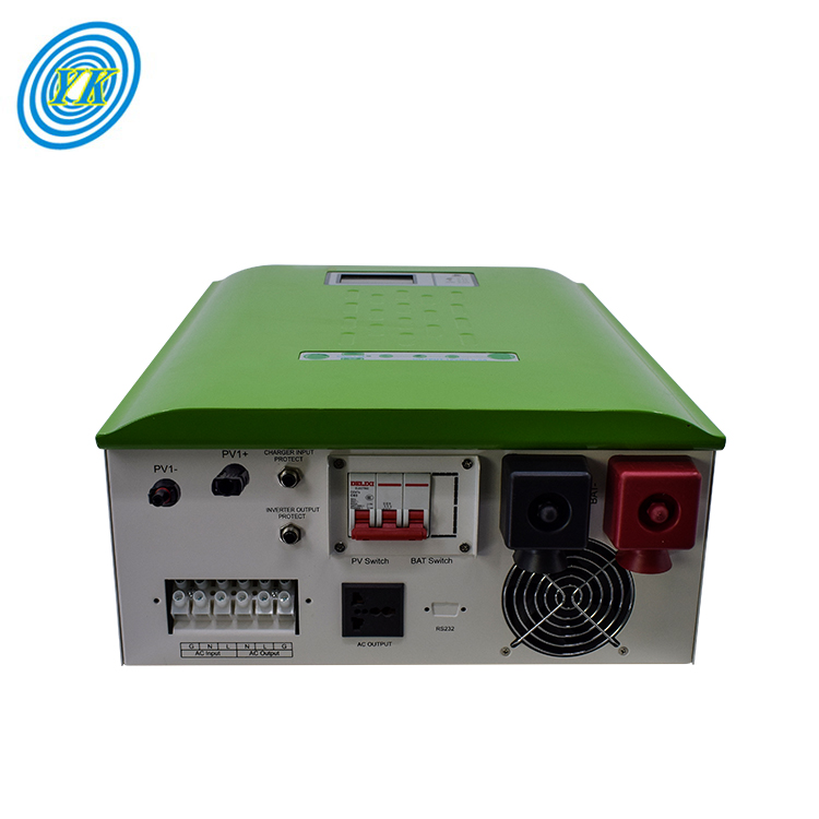
Harnessing Solar Power: The Evolution and Impact of Inverters with Built-in MPPT Technology
Click: 737 Date: 01/12/2024 2::36::33 PM
Harnessing Solar Power: The Evolution and Impact of Inverters with Built-in MPPT TechnologyThe MPPT solar inverter stands as a pivotal component in modern solar energy systems, enhancing the conversion efficiency of power from solar panels. This advanced device is pivotal in transforming the direct current (DC) produced by photovoltaic cells into an alternating current (AC) that is usable for both residential and commercial purposes.The core functionality of an MPPT solar inverter lies in its ability to continuously track the solar array's maximum power point. This dynamic tracking allows the inverter to adapt the voltage and current from the solar panels to ensure that they function at their peak efficiency level, regardless of variations in environmental conditions such as temperature changes or shading.The key advantages of integrating an MPPT solar inverter into a solar setup include:Enhanced Efficiency: MPPT inverters can elevate the efficiency of a solar power system, sometimes by as much as 30%, enabling a higher electricity yield from the same solar panel array.Environmental Adaptability: These inverters adeptly handle inconsistent weather and shading, adjusting to maintain optimal performance.Increased Energy Production: The efficiency gains from MPPT technology lead to more energy generation, optimizing the solar power system's productivity and cost-effectiveness.Monitoring Capabilities: MPPT inverters often come equipped with remote monitoring features, providing real-time data on system performance accessible via smartphones or computers.System Longevity: The precise power control offered by MPPT can potentially extend the service life of solar panels by mitigating system stress.MPPT solar inverters are versatile, finding applications across various domains, from household rooftops to commercial and industrial installations. Their capacity to maximize energy harvest under diverse conditions makes them a universal solution for solar energy conversion.When selecting an MPPT solar inverter, consider the following:Inverter Capacity: Match the inverter’s power capacity with that of your solar panel system.Brand and Quality: Choose inverters from reputable manufacturers known for their reliability and performance.Warranty: A substantial warranty period is often indicative of the manufacturer's confidence in their product.Monitoring Options: Prefer inverters that offer monitoring solutions that align with your monitoring preferences and requirements.In summary, the MPPT solar inverter is not merely an accessory; it's the intellect of the solar power system, fine-tuning efficiency and maximizing output. As the quest for sustainable energy solutions intensifies, the MPPT solar inverter emerges as a key facilitator, ensuring that solar power systems operate at their highest potential, paving the way for a cleaner, energy-efficient future.Incorporating MPPT functionality directly into solar inverters involves a multi-faceted approach to design that ensures efficient energy conversion, system stability, and adaptability to varying environmental conditions. Here are some key considerations:MPPT Algorithm Selection and Implementation: A pivotal aspect is choosing an effective MPPT algorithm, like Perturb & Observe or Incremental Conductance, which dynamically adjusts the voltage or current to locate the solar array's maximum power point under varying irradiance and temperature.System Topology and Component Selection: Designing the system requires selecting the right combination of solar panels, inverters, and other components such as charge controllers and batteries. The topology should support the integration of MPPT in a way that maximizes power extraction without compromising the system's reliability or safety.Real-time Monitoring and Control Systems: To ensure the MPPT operates at peak efficiency, real-time monitoring of solar panel voltage and current is necessary. This involves using sensors and microcontrollers to adjust the duty cycle of power converters like buck converters, which regulate the power flow from panels to the load or battery storage.Hardware Implementation and Testing: Physical implementation of the MPPT-integrated inverter requires careful hardware design, including voltage and current measurement sections, microcontroller sections for algorithm execution, and DC-DC converter sections for effective power conversion.Environmental Adaptability and Efficiency: The design must account for the nonlinear relationship between irradiance, temperature, and the location of the maximum power point. The system should be robust enough to deliver high performance across different environmental conditions and maintain efficiency whether connected to the grid or in off-grid applications.By considering these factors, designers can create a solar inverter with built-in MPPT that effectively maximizes power output from photovoltaic systems, thereby increasing overall system efficiency and reliability.Inverters with built-in Maximum Power Point Tracking (MPPT) technology have evolved to enhance the efficiency of solar systems. One notable advancement in this area is the introduction of three-phase string inverters that integrate MPPT. These inverters offer several advantages:Maximized Energy Harvest: By using advanced algorithms to continuously track the maximum power point, three-phase string inverters with built-in MPPT can extract maximum energy from the solar array, improving the system's energy yield and performance.Scalability and Flexibility: These inverters can handle a variety of solar panel configurations and string lengths, making them suitable for both residential and commercial applications, from small rooftop setups to large solar farms.High Power Conversion Efficiency: Through sophisticated digital signal processing and MPPT techniques, they constantly adjust the power output based on solar irradiance and temperature variations, ensuring efficient power conversion and reducing energy losses.Advanced Monitoring and Control: Equipped with comprehensive monitoring and control features, three-phase string inverters allow for real-time tracking of energy production, voltage, and current levels. Remote monitoring and system management are also possible, offering insights for system optimization.Reliability and Durability: These inverters are designed to withstand harsh environmental conditions, ensuring stable operation over the long term. Safety features such as overvoltage and overcurrent protection contribute to the system's longevity and protect against electrical faults.In summary, three-phase string inverters with built-in MPPT technology offer a robust solution for solar power conversion, addressing energy efficiency, adaptability, and system reliability, making them an excellent choice for optimizing solar energy conversion in various applications.When MPPT (Maximum Power Point Tracking) technology is integrated into an inverter, it brings several benefits that enhance the overall performance and efficiency of solar power systems:Enhanced Power Generation: Inverters with built-in MPPT are adept at ensuring solar panels consistently deliver power at their optimal performance levels. They achieve this by dynamically adjusting to the solar panels' ever-changing conditions to harness the maximum available energy from the sunlight.Responsive to Environmental Variations: The built-in MPPT makes the inverter responsive to various environmental factors such as temperature fluctuations, changes in solar irradiance, and partial shading. This responsiveness helps maintain high efficiency in power generation despite these potential disruptions.Minimization of Energy Loss: With precise tracking capabilities, inverters with integrated MPPT reduce energy losses that might occur due to mismatch or suboptimal operating points. This means that a greater proportion of the solar energy captured by the panels is effectively converted into usable electrical power.Streamlined Solar System Architecture: The inclusion of MPPT within the inverter simplifies the design of the solar power system by eliminating the need for separate charge controllers. This not only reduces the complexity and potential cost of the solar setup but also streamlines the installation process.Effective System Monitoring: The integration of MPPT within inverters allows for advanced monitoring of the power production process. This ensures that the system's performance can be closely observed, and any necessary adjustments can be made to maintain high efficiency under all operating conditions.In summary, the integration of MPPT into inverters significantly improves the operational efficiency of solar power systems by optimizing energy harvesting, adapting to environmental changes, reducing power loss, simplifying system design, and enabling effective monitoring.The integration of MPPT into smart inverters is a pivotal development in renewable energy technology, particularly as the world moves towards a more sustainable and resilient power grid. Smart inverters equipped with MPPT are not just passive components; they actively manage power flow, optimize solar panel output, and contribute to grid stability. These advanced inverters are an integral part of the shift towards a grid that can seamlessly incorporate a higher proportion of renewable sources, such as solar and wind.With the increased adoption of renewables, the role of grid-forming inverters is becoming more significant. Unlike traditional grid-following inverters that require a stable grid signal to operate, grid-forming inverters can initiate and control a power network independently. This quality is especially important for restoring power in the event of blackouts and for operating in microgrids, which are smaller, localized networks of electricity consumers with their own power resources.Recent advancements in grid-forming inverter technology have focused on developing robust hardware, sophisticated software, and precise control mechanisms. These innovations are crucial for ensuring that inverters can not only manage the variable output from renewable sources but also meet regulatory and technical standards, which are evolving alongside the technology.To further advance the capabilities of smart inverters with MPPT, researchers and industry professionals are working on refining modeling techniques and proposing new regulatory frameworks to facilitate the integration of these technologies into larger and more complex electric grids. The vision for the next few decades includes a power system architecture that fully leverages the benefits of grid-forming inverters, allowing for a more dynamic and self-sufficient grid that maximizes the use of renewable energy.

In-Depth Analysis of Plating Rectifiers: Functionality, Components, and Advanced Technologies
Click: 655 Date: 01/11/2024 2::54::25 PM
In-Depth Analysis of Plating Rectifiers: Functionality, Components, and Advanced TechnologiesIn the subsection titled "The Essence of Electroplating Rectifiers," we would focus on the fundamental role that plating rectifiers play in the electroplating industry. Essentially, these devices are responsible for the critical conversion of alternating current (AC) into direct current (DC), which is necessary for the deposition of metal coatings onto various substrates. This conversion is crucial as direct current is required to facilitate the electrochemical reaction that leads to metal deposition.Plating rectifiers are designed to ensure a consistent and controlled flow of electricity, which is vital for achieving a uniform and high-quality metal coating. By managing the polarity of the current, rectifiers dictate the direction in which metal ions move, thus ensuring that they are deposited correctly onto the workpiece. This careful control of current flow not only improves the aesthetics of the coated item but also enhances its functional properties, such as corrosion resistance and electrical conductivity.Furthermore, the devices are engineered to minimize the fluctuations in current, commonly known as 'ripple', which if unchecked, can lead to defects in the plating quality. By providing a stable and smooth direct current, rectifiers contribute to the consistency and reliability of the metal deposition process.In addition to these core functions, rectifiers are also recognized for their energy efficiency. The modern designs incorporate advanced technologies that allow for the conversion of AC to DC with minimal power losses, which not only reduces operational costs but also contributes to a safer and cooler working environment, lessening the need for extensive cooling systems.This section would therefore highlight how plating rectifiers serve as the backbone of electroplating processes, enabling precise control over the metal deposition, ensuring the quality of the final product, and contributing to the overall efficiency and safety of plating operations.The subsection "Components and Circuitry" would explore the intricate architecture and operational mechanics of plating rectifiers. These devices, pivotal in the electroplating process, are engineered to convert alternating current (AC) into the direct current (DC) necessary for metal deposition.Transformers: Transformers serve as the voltage regulators in rectifiers, adjusting the high voltage from power utilities to the lower voltages typically used in electroplating. They consist of primary and secondary coils, where the voltage reduction is determined by the ratio of the number of windings on these coils.Semiconductors and Diodes: Semiconductors, commonly made of silicon, are essential for the rectification process, allowing the flow of electricity in one direction and blocking it in the other, thus converting AC to DC. Diodes are the simplest form of these semiconductors, acting as one-way valves for electrical current.Silicon-Controlled Rectifiers (SCRs) and Thyristors: SCRs, or thyristors, are specialized semiconductors that not only rectify AC to DC but also regulate the output. They require a control signal and are utilized in both the transformation and regulation stages of the rectification process, depending on whether they are situated on the primary or secondary side of the transformer.Ripple Control: Despite the effectiveness of SCRs, they can introduce a distortion known as "ripple" into the DC output. This is a residual fluctuation from the AC waveform. While some plating processes can tolerate a certain level of ripple, others require additional filtering to achieve a smoother DC output.Cooling Systems: Given the heat generated during rectification, cooling systems are integral to maintaining rectifier longevity. These systems can be based on air or water cooling methods, depending on the rectifier's design and the environmental conditions in which it operates.This part would outline the key control features present in plating rectifiers, including the regulation of voltage and current, as well as the importance of waveform adjustments to ensure the precision of electroplating processes. Here's a detailed explanation:Voltage and Current Regulation: Plating rectifiers must accurately control the output voltage and current to ensure that the electroplating process proceeds correctly. The regulation of voltage and current is crucial because it affects the rate at which metal ions are deposited onto the substrate. For instance, in some plating applications, a constant voltage is needed to maintain a steady flow of ions, while in others, a constant current is necessary to deposit a uniform layer of metal.Semiconductor Technology: Modern plating rectifiers utilize semiconductor components, such as diodes and silicon-controlled rectifiers (SCRs), to filter alternating current (AC) and convert it to direct current (DC). SCRs, which are a type of thyristor, are particularly useful because they can act as both regulators and rectifiers, depending on their placement in the rectifier circuit. They are controlled by a gate signal and are essential for adjusting the output based on the plating requirements.Ripple Control: A key challenge in rectification is managing the "ripple" or the residual AC component in the otherwise smooth DC output. For high-precision plating processes, especially when working with precious metals or alloys, a low ripple rate is essential. Rectifiers designed for such applications often come with built-in filters to smooth out the ripple, ensuring consistent plating quality.Waveform Configuration: The waveform of the rectified current can significantly impact the quality of plating. Full-wave rectification is commonly preferred in many plating processes because it efficiently utilizes both halves of the AC cycle. However, the choice of waveform can depend on specific plating applications, such as chromium electroplating, which may not work well with a half-wave rectifier.Integrated Controls and Protection: Advanced plating rectifiers come with various control mechanisms, such as automatic voltage and current controls, ampere-hour control, and current density control. These features simplify the plater's work by delivering a consistent output. Additionally, rectifiers are equipped with overload protection and cooling devices, like water cooling systems or fans, to ensure safe and reliable operation.These control features are integral to the operation of plating rectifiers, enabling them to provide the precise electrical characteristics required for different types of electroplating.In the context of maintaining and enhancing the efficiency of plating rectifiers, the following points have been synthesized and rewritten from the provided sources:Effective Thermal Management: Crucial to rectifier longevity is the management of heat generated during operation. Excessive heat can cause component damage and reduce efficiency. To prevent this, ensure semiconductors and other power components are well-maintained and cooling pathways remain unobstructed to facilitate heat dissipation [1].Routine Cleaning and Component Inspection: Monthly maintenance activities are essential. This includes cleaning intake and output screens with a vacuum and inspecting all high-current conducting connections for secureness, as loose connections can cause voltage drops, overheating, and potential component failure [2].Cooling System Importance: Cooling systems, comprising fans, heat sinks, and coolant systems, are pivotal in maintaining rectifiers at operational temperatures. Regular maintenance of these systems, including inspections and cleanings, prevents overheating and extends equipment lifespan [3].Proactive Maintenance and Diagnostics: Regular checks of air filters, secure fan blades, and control instrumentation, along with onboard diagnostics, help in identifying trouble areas early, reducing downtimes and prolonging rectifier service life [5][6].Energy Efficiency Considerations: Rectifiers with efficient circuitry, such as three-phase bridge circuits, can significantly reduce energy consumption. Additionally, investing in quality cooling systems and maintaining them can result in energy savings and improved system performance [2].These points emphasize the importance of a proactive approach to maintenance and efficiency in the operation of plating rectifiers. Regular maintenance not only ensures the proper functioning of the rectifier but also contributes to energy conservation and cost savings over time.In this section, we'll delve into the advanced capabilities and diverse uses of plating rectifiers, highlighting technological innovations such as computer-controlled operations, the precision of pulse plating, the versatility of periodic reverse techniques, the uniformity benefits of anodizing, and the broad range of industrial applications these features support.Computer-Controlled Rectifiers: Modern rectifiers are now increasingly integrated with computer systems, allowing for more precise control over the plating process. Digital controls can fine-tune amperage and voltage, provide ramp-up sequences as parts enter tanks, and shut down with exact timing. This level of control enables consistent metal thickness and quality, with the added benefits of automated process monitoring and reduced manual intervention.Precision of Pulse Plating: Pulse plating uses interrupted direct current to deposit metal in a controlled manner. This technology allows for denser deposits with finer grain structures, which can be applied more quickly than traditional methods. It often requires less in the way of plating-solution additives, which can lead to cost savings. Pulse plating is not only used in the electronics industry but has also found applications in electropolishing, anodizing, electrocleaning, and barrel plating.Versatility of Periodic Reverse: Periodic reverse plating involves alternating the current direction at set intervals, which can help in the redistribution of material on a plated surface, leading to improved uniformity and throwing power. This technique can be particularly effective when working with complex geometries or when trying to achieve specific surface characteristics.Uniformity Benefits of Anodizing: Anodizing processes often use rectifiers to provide the required electrical power. For certain types of anodizing, such as hard-coat anodizing, higher voltages are necessary, and rectifiers are designed to deliver these safely and consistently. The controlled electrical supply from rectifiers ensures uniform anodic films and can be adjusted for specific coloration techniques.Industrial Applications: The advanced features of modern rectifiers have expanded their use beyond traditional plating. They are now instrumental in various industries, from aerospace and automotive to consumer electronics and medical devices. The ability to control plating processes with high precision makes these rectifiers crucial for producing high-quality, reliable, and durable coatings.

Comprehensive Guide to Selecting and Utilizing Adjustable DC Power Supplies
Click: 793 Date: 01/10/2024 2::16::17 PM
Comprehensive Guide to Selecting and Utilizing Adjustable DC Power SuppliesProgrammable power supplies are sophisticated devices that offer meticulous control over their output parameters. They are an indispensable asset in numerous applications where precise power regulation is necessary. Here's an overview of their features and capabilities based on the information from the sources:Precision Control: Programmable power supplies deliver exact control over voltage and current, with some models allowing the setting of complex output profiles. This is crucial for applications that demand specific power conditions, such as testing electronic components or conducting research experiments.Customizable Profiles and Automation: Users can tailor the power supply's output to the unique requirements of different devices or scenarios. Moreover, the ability to automate these power supplies through software enhances efficiency, reduces human error, and supports unattended operations.Remote Operation and Interfaces: Many programmable power supplies come equipped with interfaces such as USB, Ethernet, or GPIB, enabling remote operation. This is particularly useful in situations where direct access to the power supply is limited or when remote monitoring and management are needed.Safety Mechanisms: To prevent damage to connected devices, programmable power supplies often incorporate safety features like overvoltage and overcurrent protection. These mechanisms are designed to act swiftly in the event of a power surge or abnormal output conditions.Efficiency and Energy Savings: High-efficiency designs are common in programmable power supplies, which not only minimize energy consumption but also reduce the heat generated by the device, contributing to a more sustainable operation.When selecting a programmable power supply, it's essential to consider factors such as the voltage and current ranges, programmable features, output stability, and cooling methods. Whether you need a power supply for a laboratory setting, product development, or manufacturing tests, programmable power supplies offer the versatility and control necessary for a wide array of applications.To address the topic of "Safety and Protection Features" for adjustable DC power supplies, we can highlight several critical elements that ensure the safe operation of these devices:Overvoltage Protection: This feature helps prevent damage to both the power supply and the connected devices by shutting down the power or restricting the voltage output when it exceeds a predetermined thresholdOvercurrent and Short Circuit Protection: By monitoring the current flow, the power supply can disconnect the circuit if the current exceeds safe levels or if a short circuit is detected, thereby preventing potential damage or fire hazardsThermal Management: Advanced power supplies are equipped with thermal shutdown mechanisms that automatically power down the unit or reduce its performance to prevent damage when excessive heat is detectedGround Fault Interruption (GFI): GFI is designed to protect users from electric shock by interrupting the power supply when a fault current to ground is detectedCertification and Standards Compliance: Compliance with industry standards and certifications, such as UL listing, ensures that the power supply has passed rigorous safety tests and adheres to established safety guidelinesThese features work together to create a robust safety net for adjustable DC power supplies, ensuring that they operate reliably and prevent harm to users and equipment in the event of a fault or abnormal operation.User-friendly interfaces in adjustable DC power supplies are designed to simplify programming and operational control. These interfaces often come with intuitive controls and clear visual indicators, making it easier for users to configure and modify supply parameters. With the advancement of digital remote control, users can automate repetitive tasks, record operational data, and synchronously control multiple power supplies or integrate their operation with other devices, as described by Matsusada Precision.Moreover, the integration of standard programming languages and drivers, such as SCPI commands and IVI drivers, allows for increased portability and versatility across different devices. This standardization means that users can program devices without having to focus extensively on unique port configurations, as highlighted in the programming guide for remote control of power supplies by Matsusada Precision.Furthermore, power supplies like the Rigol DP832 offer advanced features accessible through the front panel, such as timer functions, output waveform construction, and user-defined start-up interfaces. These features, along with remote control options via USB, LAN, GPIB, or RS232, cater to a range of user preferences for both local and remote operation. The inclusion of built-in help systems and the ability to lock keys to prevent inadvertent changes further improve the usability and safety of such instruments.In summary, adjustable DC power supplies are becoming increasingly user-friendly with interfaces that support easy programming, enhanced safety features, and the ability to be controlled remotely. The development of software and the use of standardized commands contribute to a more accessible and efficient user experience.To ensure reliable performance and consistent power delivery from an adjustable DC power supply, it's imperative to focus on the following aspects:Design Robustness and Conservative Approaches: The electrical design should be robust, incorporating conservative component specifications that exceed the minimum requirements. This would include accounting for potential load and line transients, as well as electromagnetic interference (EMI) and noiseComponent Quality and Selection: High-quality components with proven reliability should be selected, considering their compatibility with both the design and the manufacturing process. Special attention should be given to components like capacitors, which are common failure points in power suppliesThermal Management: Effective thermal management is crucial for maintaining component reliability. This involves careful planning of cooling strategies to minimize temperature rise and thermal cycling, which could otherwise accelerate component wear-outManufacturing Consistency: A consistent and controlled manufacturing process helps ensure that each power supply unit meets the intended design specifications and reliability standardsReliability Testing and Assessment: Conducting thorough reliability testing, such as Highly Accelerated Life Testing (HALT) and Highly Accelerated Stress Screening (HASS), can help identify potential failure points and improve the overall reliability of the power supplyBy addressing these key factors, manufacturers can deliver adjustable DC power supplies that offer stable, precise, and accurate performance, which is essential for a wide range of applications requiring dependable power delivery.When considering the scalability and future-proofing of DC power supply systems, it's essential to examine options that can evolve with technological advancements and increasing power demands. Modular or rack-mounted power supplies present a strategic choice for organizations that anticipate growth or changes in their power supply needs.Modular Systems: These power supplies are designed to be easily expanded by adding more modules to the existing framework, allowing for incremental increases in power capacity as needed. This approach minimizes the need for complete system overhauls when power requirements change, offering a cost-effective and less disruptive pathway to scaling up power infrastructure.Rack-Mounted Power Supplies: Rack-mounted options offer a high degree of integration and are typically designed to fit standard equipment racks. This standardization allows for better space utilization and easier upgrades, as these units can be swapped out or added to without significant modifications to the existing setup.High-Performance Rackmount DC Power Supplies: Products in this category aim to deliver a blend of compactness, low noise, and high power. They can accommodate a variety of applications, from industrial to communication fields, with the adaptability to support emerging technologies such as electric vehicles and advanced semiconductor processes.Programmable and Autoranging Features: Some rack-mounted power supplies come with autoranging capabilities and programmability, which allows for flexible power management and the ability to simulate different power scenarios. This adaptability is crucial for research and development as well as for testing a wide range of devices under various conditions.High Power in a Single Rack: Certain power supplies can deliver up to 120 kW of power within a single rack configuration. This high power density is particularly beneficial for data centers and other applications where space is at a premium and power needs are substantial.In summary, the scalability and future-proofing of power supply systems are significantly enhanced by modular designs and rack-mount configurations that accommodate evolving technology and power demands. These systems offer a way to maintain a robust power supply infrastructure that can adapt to future needs without extensive overhauls, ensuring operational continuity and cost-efficiency.
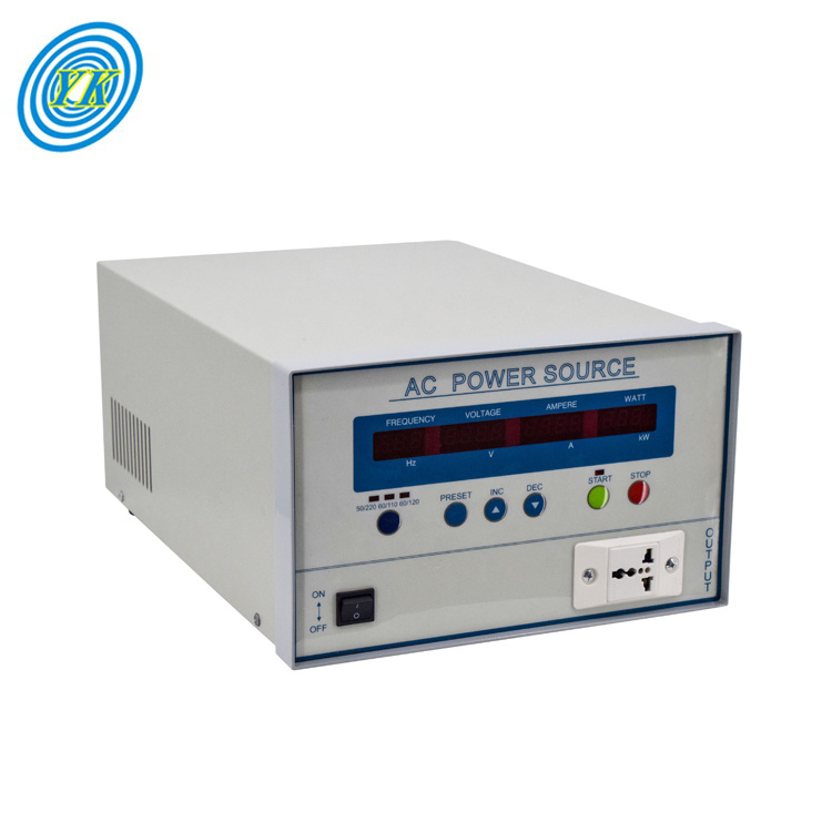
Click: 746 Date: 01/09/2024 2::09::47 PM
Advancements and Efficiency in Frequency Conversion Technologies: From Motor Control to Power QualityTo enhance motor performance using Variable Frequency Drives (VFDs), we must delve into the mechanisms by which VFDs control and improve the operation of electric motors.Optimizing Speed Control: VFDs allow precise control over motor speed by adjusting the frequency and voltage of the power supplied to the motor. This flexibility can lead to improved process control and product quality in applications where varying the motor speed is necessary.Energy Savings: By operating motors at the most efficient speed for the application, VFDs reduce energy consumption. This is especially true for applications with variable loads, where running at full speed at all times is not necessary.Extended Motor Life: VFDs can reduce the mechanical and thermal stress on motors by providing a soft start capability. This gradual ramp-up of speed can extend the lifespan of the motor by minimizing the wear and tear associated with high inrush currents at startup.Enhanced Process Control: With the ability to finely tune motor speeds, VFDs contribute to better accuracy and repeatability in processes that require precise motor speed adjustments.Reduction of Maintenance Costs: Since VFDs help in operating motors under optimal conditions, they can also lead to a reduction in maintenance costs due to fewer mechanical breakdowns and less downtime.By implementing VFDs, industries can realize significant improvements not only in the performance of their motors but also in overall operational efficiency.Understanding the Role of Inverters in Power ConversionInverters play a crucial role in power conversion, transforming direct current (DC) into alternating current (AC). This process is essential for various applications where AC power is required but only DC power is available. Here's an overview of the role of inverters in power conversion:Conversion Principle: Inverters use semiconductor devices to switch DC input on and off and generate an AC waveform. This waveform can then be filtered or modified to closely resemble the standard AC power waveform.Types of AC Waveforms: Inverters produce different types of AC waveforms, such as pure sine wave, modified sine wave, and square wave. The pure sine wave is ideal for sensitive electronic devices as it closely mimics the waveform provided by utility companies.Applications: Inverters are used in a variety of settings, including renewable energy systems (like solar panels), uninterruptible power supplies (UPS), electric vehicle drives, and any situation where AC equipment must run off batteries or other DC sources.Variable Frequency Drives: Inverters are integral to variable frequency drives (VFDs), which control the speed of an AC motor by varying the frequency and voltage of the power supplied to the motor.Efficiency and Quality: Modern inverters aim to maximize efficiency and minimize total harmonic distortion (THD) to ensure the quality of the AC power is maintained.High Voltage Direct Current (HVDC) Transmission: Inverters are also used in HVDC power transmission systems, where they convert high-voltage DC back into AC for distribution.In summary, inverters are versatile devices essential for converting DC to AC, enabling the use of AC appliances and equipment in environments where only DC power is available, and contributing significantly to the control and efficiency of electric power systems.The Impact of Pulse Width Modulation on Frequency Conversion EfficiencyPulse Width Modulation (PWM) is a powerful technique used in electronic circuits to control the amount of power delivered to a load without significant power loss. It achieves this by varying the width of the pulses in a signal, hence the term "pulse width modulation." This modulation method is particularly effective in applications such as motor control and LED dimming, where it enables precise control over speed and brightness respectively.PWM operates by switching the power to a device on and off at a high frequency with a variable duty cycle. The duty cycle is the percentage of one period in which a signal or system is active. A higher duty cycle increases the amount of power delivered to the load, while a lower duty cycle reduces it. This rapid switching with a variable duty cycle means that the device receives a series of pulses rather than a constant voltage or current, allowing finer control over its operation.One of the key characteristics of PWM is the frequency at which the pulses are switched on and off. The frequency must be high enough so that the load, such as a motor or an LED, perceives a smooth, continuous signal rather than discrete pulses. For example, a low frequency could cause an LED to visibly flicker, while a sufficiently high frequency would make the light appear stable.The efficiency of frequency conversion in PWM systems is largely due to the fact that power loss is minimized during the switching process. When the switch is off, there is almost no current, and when it is on, there is very little voltage drop across the switch. This results in very low power loss, making PWM an efficient way to control power delivery to a load.In addition to efficiency, PWM is highly compatible with digital technology, which operates in discrete states (on/off). This makes it simple to implement PWM control using digital circuits, which can easily adjust the duty cycle to achieve the desired level of control.In summary, the impact of PWM on frequency conversion efficiency is significant due to the precise control it offers and the minimal power loss during the switching process. This makes it an indispensable technique in modern electronics where power efficiency and fine control are paramount.The Impact of Pulse Width Modulation on Frequency Conversion EfficiencyPulse Width Modulation (PWM) significantly influences the efficiency of frequency converters by controlling the average power delivered to a load without the substantial power loss associated with resistive methods. PWM achieves this by rapidly switching the power source to the load on and off, with the relative on-time known as the duty cycle. The duty cycle, represented as a percentage of the total cycle time, directly affects the average voltage and current reaching the load, thus controlling the power without changing the voltage source.The frequency of the PWM signal is equally crucial. It must be high enough to prevent the load, particularly inertial loads like motors or perceptual loads like LEDs, from reacting to the switching itself, thereby ensuring a smooth operation. For example, a low-frequency PWM signal could cause a motor to exhibit a surging behavior, while a high-frequency signal would maintain a steady motor speed or a stable LED brightness level.PWM's efficiency comes from the fact that during the 'off' phase of the cycle, there is minimal current flow, and during the 'on' phase, there is almost no voltage drop across the switch. This results in very low power losses during the switching process. Additionally, since digital circuits inherently operate in on/off states, they are particularly well-suited for generating and controlling PWM signals, allowing precise control over the duty cycle.Furthermore, PWM is utilized in various applications, such as variable frequency drives (VFDs) for AC motor speed control, where the PWM signal is used to emulate an AC waveform by varying the polarity of the output voltage. This allows for efficient motor speed regulation by changing the frequency of the AC signal rather than its amplitude, thereby improving energy efficiency and control precision.The design and analysis of circuits utilizing PWM require careful consideration of both the duty cycle and frequency to ensure efficient and effective power delivery to the load. Modern PCB design and analysis software can facilitate the development of these circuits, allowing engineers to optimize PWM parameters for their specific application needs.Harmonics and Electromagnetic Interference: Mitigation Strategies in Frequency ConvertersElectromagnetic interference (EMI) is a disturbance that affects an electrical circuit due to either electromagnetic induction or electromagnetic radiation emitted from an external source. The disturbance may interrupt, obstruct, or otherwise degrade or limit the effective performance of the circuit. EMI can be seen as a form of pollution in the electromagnetic spectrum that can come from natural occurrences such as solar flares or man-made sources like electrical power lines, machinery, or broadcasting towers.Electromagnetic interference can be classified based on various factors:Source of EMI: EMI can originate from natural phenomena such as lightning and solar flares or from man-made sources such as electronic devices and power lines.Bandwidth of EMI: EMI can be either broadband, which is not confined to discrete frequencies and can arise from both natural and man-made sources, or narrowband, which comes from a single or narrow band of frequencies.Duration of EMI: EMI can be continuous, emitted constantly for as long as the source and receiver are coupled, or impulse, occurring in short bursts or intermittently.Mitigation strategies for EMI in frequency converters involve several practices and design considerations:Filtering: The use of filters to block unwanted EMI signals is common. Filters can be integrated into cables, connectors, and power lines, and are essential in protecting against EMI.Grounding: Proper grounding can serve as a pathway for EMI to be safely dissipated into the Earth rather than affecting the electronic devices.Shielding: This involves enclosing sensitive electronics in materials that block EMI, such as metallic enclosures, to prevent interference.Design: Careful layout and design of electronic systems can minimize EMI. This includes minimizing the length of signal paths, using differential signaling, and avoiding loop areas that can act as antennas.Standards Compliance: Adhering to EMC (Electromagnetic Compatibility) standards and guidelines can help in designing systems that both minimize EMI emissions and are resistant to EMI.Advanced Communication Protocols: Using communication protocols that are designed to be robust against EMI can improve the reliability of data transmission in the presence of interference.It's important to note that these strategies are not mutually exclusive and are often used in combination to ensure effective EMI mitigation. For example, a frequency converter might incorporate EMI filters, be housed within a shielded enclosure, and have a design that includes proper grounding and layout to minimize the effects of EMI. Additionally, regular testing for EMC can help identify potential EMI issues before they become problematic.Addressing EMI is crucial for maintaining the reliability and efficiency of frequency converters, which play a key role in power conversion and motor speed control in various industrial and commercial applications. By implementing these mitigation strategies, engineers can design frequency converters that function effectively even in environments with significant electromagnetic disturbances.Advancements in Three-phase Converter Technologies for Industrial ApplicationsThe field of industrial applications has seen significant developments in three-phase converter technology, which have greatly enhanced the capabilities and efficiency of various systems. These advancements have been critical in addressing the complex needs of modern industry, where power conversion and motor control are pivotal for operations.One notable advancement in three-phase converters is the improvement in design and materials that has led to more compact, efficient, and cost-effective units. These modern converters are capable of handling higher power levels and provide better control over motor speeds, resulting in improved performance and energy savings.Innovations in semiconductor technology have also played a crucial role. The use of Silicon Carbide (SiC) and Gallium Nitride (GaN) transistors, for instance, has allowed for converters that operate at higher frequencies with reduced heat loss. This translates to less energy waste and a lower need for cooling systems, which can be both space-consuming and expensive.Furthermore, the integration of advanced control strategies, such as vector control and direct torque control, has improved the precision with which motors can be managed. This is particularly important in applications requiring highly dynamic performance, such as in robotics or CNC machinery.The focus on minimizing electromagnetic interference (EMI) and harmonics has led to the development of sophisticated filtering and shielding techniques. These advancements ensure that frequency converters can operate in compliance with stringent regulatory standards while reducing the potential for disruptive interference in sensitive environments.Lastly, the push towards smart and connected industrial systems has seen frequency converters being equipped with communication capabilities. This allows for better monitoring, diagnostics, and integration with industrial automation systems, paving the way for predictive maintenance and enhanced operational efficiency.All these advancements collectively contribute to a more reliable, efficient, and intelligent industrial landscape. As three-phase converter technology continues to evolve, the potential for further innovation remains vast, promising even greater contributions to industrial productivity and sustainability.
