News
Essentials of Buck/Boost DC-DC Converters: From Basic Operation to Advanced Design
Click: 768 Date: 01/16/2024 2::02::49 PM
Essentials of Buck/Boost DC-DC Converters: From Basic Operation to Advanced Design
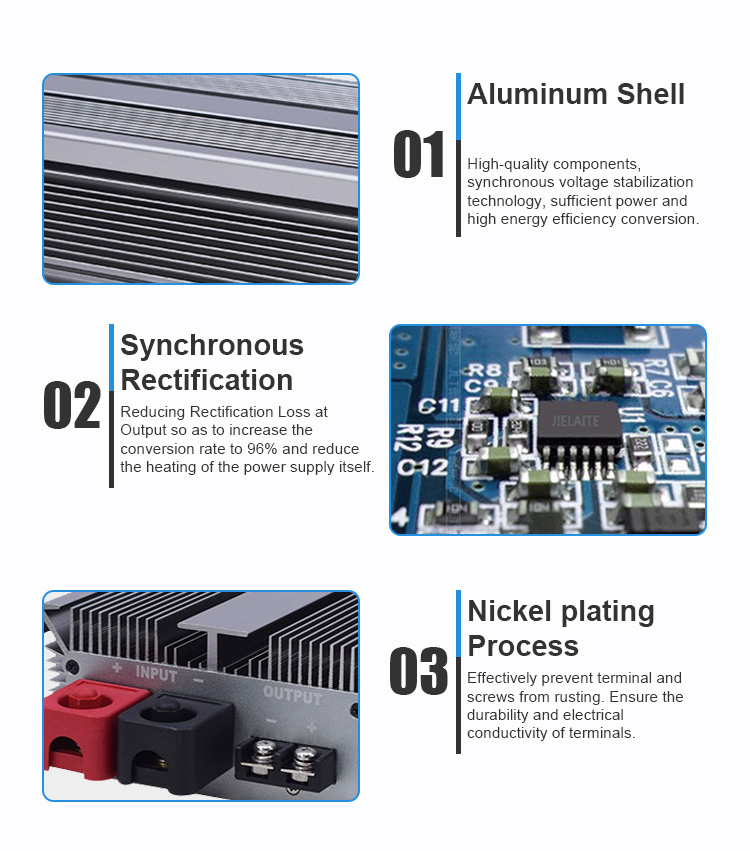
The principles of voltage conversion techniques involve transforming electrical power from one form to another while maintaining control over various parameters to ensure efficiency and safety. The conversion process typically includes several key steps:
Input Voltage and Frequency Adjustment: This involves modifying the input voltage and frequency to levels suitable for the system's circuitry. For instance, an input transformer can step down high AC line voltage to a more manageable low voltage level required by the system.
Current Rectification: This step converts the adjusted AC voltage into DC voltage using input rectifiers.
Voltage Smoothing: After rectification, the output typically contains ripples, which are smoothed out using capacitors to provide a steady DC level.
Output Voltage Regulation: Voltage regulators ensure that the output voltage remains constant despite variations in line voltage, load, and temperature changes. This is crucial for maintaining the reliability and performance of electronic devices.
Isolation: Electrical isolation between the input and output of the power supply is necessary for safety and noise reduction. This can be achieved through transformers or optocouplers.
Efficiency and Power Density: Switching power supplies are favored in many applications due to their high efficiency and compact size. They use high-frequency switching techniques to control the energy transferred to the output.
Output Ripple: The trade-off with switching supplies is typically a higher output ripple compared to linear supplies. However, this can be mitigated through additional filtering.
Input Voltage Range: Switching power supplies can operate over a wide input voltage range without significantly affecting efficiency, making them versatile for various applications.
Transient Response: These supplies may have slower transient response times compared to linear supplies but can provide better performance during voltage sags (brownouts).
Power Factor Correction: To minimize energy loss in power distribution systems and meet utility requirements, power factor correction may be employed in the design of power supplies.
Protection Features: Power supplies are designed with features to protect against overcurrent, overload, and short circuits to ensure safe operation under fault conditions.
These principles are fundamental to the design and operation of power conversion devices like AC/DC power supplies, DC/DC converters, and DC/AC inverters. Each step in the conversion process is critical and requires careful consideration to achieve the desired performance and efficiency while ensuring the safety and reliability of the power supply.
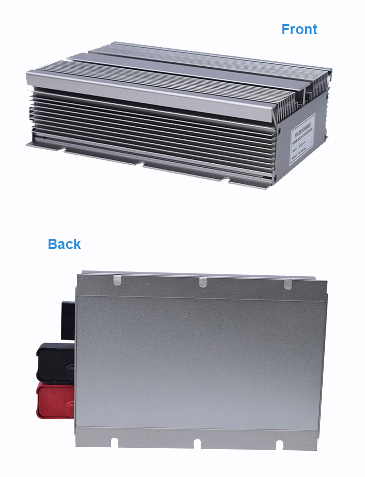
Efficiency and control in power regulation involve balancing the demands of delivering reliable power while optimizing the use of resources and maintaining costs. This topic can be explored through various angles:
Maximizing Efficiency in Power Systems: This involves using technology and processes to ensure that power delivery is done with minimal waste and maximum utility. Techniques such as advanced metering infrastructure (AMI) and demand response help utilities to match supply with demand and reduce losses
Control Mechanisms in Power Distribution: Power regulation requires sophisticated control systems to manage the flow of electricity and maintain stability. Control mechanisms include automated switchgear, capacitor banks for reactive power management, and voltage regulators to ensure consistent service quality
Cost Management and Economic Utilization: Effective power regulation requires strategies to control costs without compromising quality. This involves strategic investments in infrastructure, optimizing operational costs, and implementing energy-efficient technologies
Adapting to Technological Advancements: The power industry is continuously evolving with new technologies such as smart grids, renewable energy integration, and battery storage systems. Regulators must adapt policies and control mechanisms to embrace these changes while ensuring security and reliability
Regulatory Framework and Policy Making: The regulatory environment plays a critical role in power regulation. It involves setting tariffs, ensuring fair competition, and promoting policies that support sustainability and innovation in the power sector
These aspects are crucial for a stable, efficient, and cost-effective power regulation system that meets the needs of consumers and supports the growth of the energy sector.
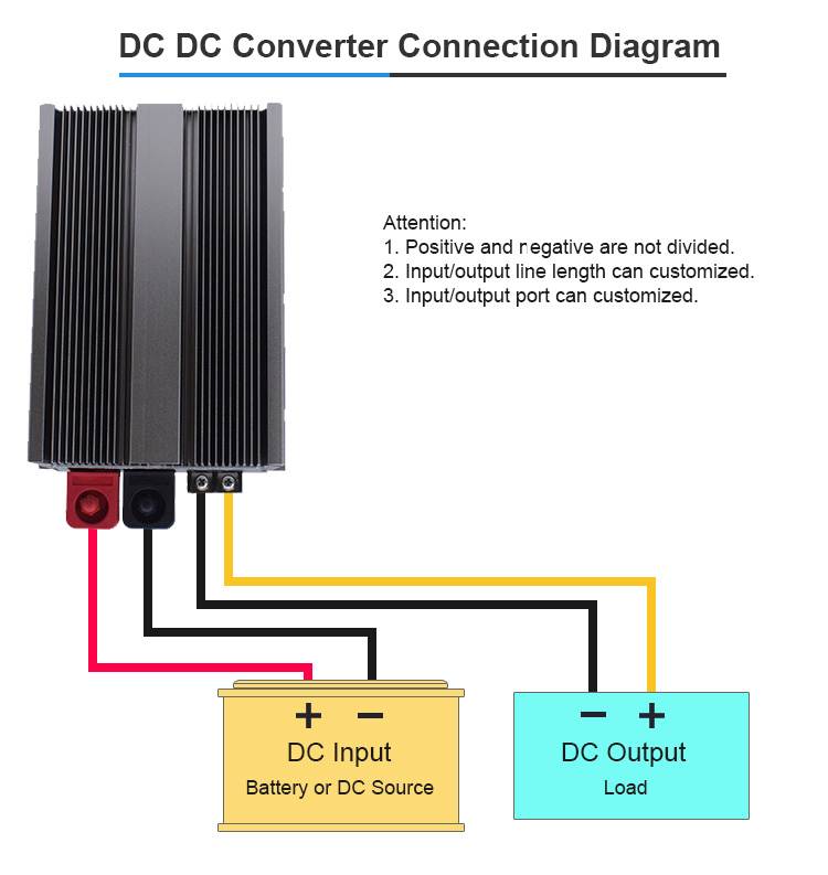
DC-DC Converters, particularly in Buck/Boost types, can be addressed by looking at various aspects of fault management and protection features in power electronics systems. Here are some key points that could be discussed under this heading:
Fault Types and Diagnosis: Addressing the various types of faults that can occur in a power system, such as short circuits, overloads, and open circuits. Techniques for diagnosing these faults include monitoring current and voltage levels or using algorithms to detect irregular patterns indicative of a fault condition.
Protection Mechanisms: Discussing the hardware and software mechanisms that are in place to protect against faults, such as fuses, circuit breakers, and solid-state protection devices. These mechanisms can isolate faults to prevent damage to other system components.
Fault Response Actions: Outlining the typical responses to fault conditions, such as shutting down the converter, entering a safe mode, or switching to a redundant system to maintain operation despite a fault.
Design for Reliability: Exploring design considerations that enhance the reliability of Buck/Boost converters, such as component derating, use of robust components, and thermal management to prevent overheating, which is a common cause of failure.
Fault Tolerant Topologies: Presenting topologies for DC-DC converters that are inherently more tolerant to faults, including those that can reconfigure themselves to bypass damaged components or those that use redundancy to maintain operation after a fault.
Monitoring and Telemetry: Discussing the importance of system monitoring and telemetry to provide real-time data on system performance. This data can be used for predictive maintenance and to quickly identify when and where a fault has occurred.
Ground Rules and Requirements: Establishing a set of ground rules and requirements for fault protection design, ensuring that the system can maintain a safe state for a predetermined period following any anomaly, and that sufficient information is available for failure analysis and recovery actions.
Autonomous Fault Protection: The implementation of autonomous fault protection to monitor, detect, and resolve faults as they occur, thereby preserving the overall health of the system and providing greater diagnostic capabilities.
These points cover the spectrum of considerations and strategies involved in fault management and protection for power electronics systems like Buck/Boost DC-DC converters. They emphasize the importance of anticipating potential faults, designing systems to withstand them, and having robust mechanisms in place to deal with them when they occur.
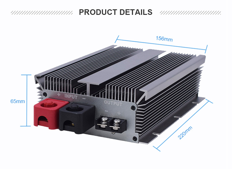
Buck-boost DC-DC converters play a critical role in energy storage systems by efficiently managing the voltage supplied to or from energy storage elements such as batteries, capacitors, or fuel cells. These converters adapt the voltage levels to match the specific requirements of the storage devices, ensuring optimal charging and discharging processes, as well as maximizing the lifespan and performance of the storage units.
In renewable energy applications, such as solar or wind power systems, buck-boost converters help in stabilizing the fluctuating power output from these sources before it's stored or used. They ensure that the voltage levels are appropriate for charging batteries or for integration into the grid.
In electric and hybrid vehicles, which rely on batteries for propulsion, buck-boost converters are essential for voltage regulation. They adjust the voltage levels to suit the needs of the vehicle's electrical system, enhancing the overall efficiency and reliability of the vehicle's power supply.
In portable electronic devices, these converters optimize battery life by adjusting the voltage levels to the varying demands of the device. This ensures that the device operates effectively even as the battery voltage changes due to discharge.
Moreover, in any DC microgrid scenario, buck-boost converters are pivotal in maintaining stable voltage levels for a variety of loads and sources, contributing to the overall resilience and efficiency of the microgrid system. They allow for seamless power flow between different voltage domains within the microgrid, facilitating the integration of diverse energy sources and storage solutions.
When designing the layout for a switching regulator, such as a buck-boost DC-DC converter, there are several key considerations to ensure optimal performance and reliability. Here is a summary of the crucial design considerations:
Grounding Strategy: Develop a solid grounding strategy to minimize noise and ensure stable operation. Segregate the analog and power grounds when possible, connecting them at a single point to prevent high-amplitude currents from the power section interfering with sensitive analog circuits .
Component Placement: Place components strategically to minimize the loop areas of high-frequency current paths. Components with discontinuous current, like the switch node, should be placed close together to reduce stray inductance and associated EMI .
Bypass Capacitors: Utilize high-frequency bypass capacitors on the supply pins of IC devices. Place these capacitors as close as possible to their respective pins and connect them to a clean, low-inductance ground .
Trace Layout: Use wide traces for power paths to reduce resistance and improve efficiency. Keep high-current traces short to minimize inductance and reduce voltage spikes and ringing .
Minimizing EMI: Be mindful of the placement and routing of components to reduce electromagnetic interference. This includes careful positioning of inductors and transformers to minimize radiated noise .
Feedback Networks: Place voltage divider resistors used for feedback close to the feedback pin of the regulator to minimize noise coupling through capacitive effects .
Thermal Management: Design the layout to accommodate heat dissipation, including the use of heatsinks or thermal vias if necessary, especially for components like power switches that may generate significant heat .
Use of Layers: On multi-layer boards, consider using an inner layer as a shield to reduce interference and utilize multiple vias in parallel to lower resistance and inductance for power connections .
Input and Output Capacitors: Place input and output capacitors close to their respective loops to contain high-frequency currents and minimize their interference with other parts of the circuit.
By adhering to these guidelines, you can create a robust and efficient layout for a buck-boost switching regulator that will perform well across a range of operating conditions.