News
Enhancing Performance and Safety in Isolated DC-DC Converters: From Industrial to Military Applications
Click: 1017 Date: 01/17/2024 4::53::57 PM
Enhancing Performance and Safety in Isolated DC-DC Converters: From Industrial to Military Applications
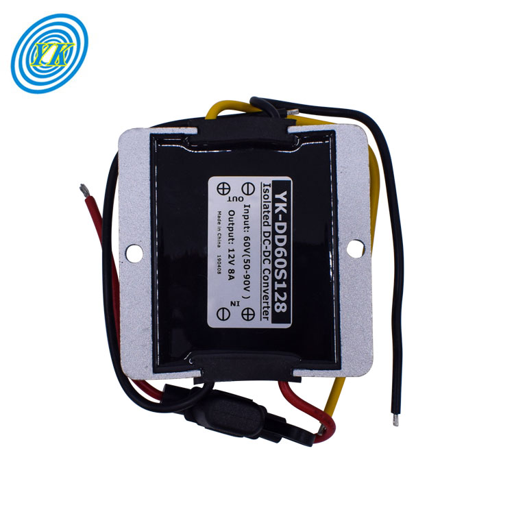
Galvanic isolation in DC-DC converters is crucial for both safety and functional reasons, as it separates the input and output electrically, preventing dangerous high voltages from affecting the low voltage side. With advances in technology, galvanic isolation techniques have significantly improved, enhancing the performance and reliability of isolated DC-DC converters.
1. Introduction to Galvanic Isolation in DC-DC Converters
Galvanic isolation is the practice of physically and electrically separating the input and output sides of a DC-DC converter. This isolation is typically achieved using a transformer, ensuring no direct conduction path exists between the input and output. Isolation is essential for safety, noise reduction, and preventing ground loops.
2. Technologies Enhancing Galvanic Isolation
Recent technologies have introduced new materials and designs for transformers and optocouplers, which are commonly used for feedback in isolated converters. High-frequency transformers have become smaller and more efficient, while optocouplers have seen improvements in speed and reliability. Silicon carbide (SiC) and gallium nitride (GaN) semiconductors are now used in some isolated converters, offering better performance at high frequencies and temperatures.
3. Improved Transformer Design and Materials
Transformers in isolated DC-DC converters have seen advancements in core materials, which reduce losses and allow for operation at higher frequencies. This has led to smaller, more compact transformers that can fit into tighter spaces without sacrificing performance. New winding techniques have also been introduced to minimize leakage inductance and improve efficiency.
4. Enhanced Isolation Techniques and Standards
Isolation techniques have improved to meet higher safety standards, such as reinforced insulation and increased working voltages. Regulatory standards like UL, IEC, and EN dictate the requirements for isolation in various applications, driving the development of more advanced isolation methods.
5. Innovations in Isolated Converter Topologies
New converter topologies have been developed to optimize the use of galvanic isolation. Advanced topologies such as the LLC resonant converter and active clamp forward converters offer higher efficiency and power density while maintaining isolation. These topologies are becoming more popular in applications that require high reliability and power conversion efficiency.
Conclusion: The Future of Galvanic Isolation
The continued innovation in materials, technologies, and topologies is pushing the boundaries of galvanic isolation in DC-DC converters. These advancements are making isolated converters more efficient, compact, and suitable for a wider range of applications, from industrial to medical and aerospace. As electronic devices become more prevalent and power conversion needs evolve, the role of galvanic isolation will remain a critical factor in the design and operation of safe and efficient power systems.
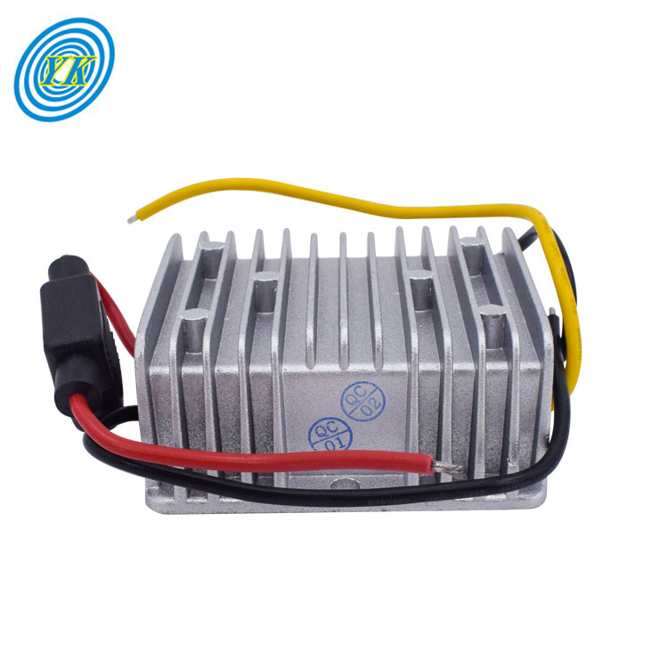
In the realm of power electronics, optimizing power efficiency is a critical aspect of designing switching converters. This article explores the methodologies and technologies instrumental in enhancing the power efficiency of switching converters.
Understanding the Thermal Challenges and Integration in Switching Converters Switching converters, which include components like controllers, converters, and modules, are subject to thermal challenges as they dissipate heat. Integration of components such as field-effect transistors (FETs) and inductors can lead to smaller sizes and ease of use, but also introduces thermal management issues. As integration increases, fewer options are available to improve efficiency, necessitating careful optimization of device operation at high ambient temperatures to minimize power loss.
The Crucial Role of MOSFETs in Efficiency Power MOSFETs, which act as switches in DC/DC converters, have parameters like on-resistance (RDS(on)) and gate charge (QG) that significantly impact efficiency. To optimize efficiency, designers need to balance between RDS(on) and switching losses. The goal is to equalize switching losses with conduction losses, which can be achieved by selecting FETs with low RDS(on) and QG, and by sizing high-side and low-side FETs to equalize conduction losses.
The Impact of Switching Frequency on Power Loss Switching frequency is a critical parameter that influences power loss in converters. Higher frequencies lead to increased switching losses, while lower frequencies result in larger inductors, which can have higher DC resistance and thus higher conduction losses. Finding an optimal switching frequency that balances these losses is key to improving efficiency.
Optimizing Inductor Selection for Efficiency The power inductor, a core component of DC/DC converters, must be carefully selected to manage ripple current and minimize losses. The choice of inductor value and the trade-off between inductor size and switching frequency are essential considerations. Inductor core losses also depend on switching frequency and core material, with different materials offering varying performance at high frequencies.
Control-Based Optimization Techniques Control-based optimization involves creating accurate mathematical models of converter operation to minimize losses. This approach involves precomputing optimal control patterns and implementing them online to improve efficiency and extend the operational range of the converter. Such optimization can lead to significant reductions in losses, especially during rapid changes in power references or during fast transients.
Automated Optimization with Voltage Input-to-Output Control (VIOC) VIOC technology enables automated control of a switching converter's output voltage, optimizing the efficiency of a downstream LDO regulator. By reducing the voltage differential across the LDO regulator, VIOC decreases power dissipation and improves system efficiency. This technology is particularly beneficial for systems with variable loads, as it can adjust the output voltage of the switching converter to maintain a constant voltage drop across the LDO regulator.
In conclusion, optimizing power efficiency in switching converters is a multifaceted challenge that requires careful consideration of thermal management, component selection, and control strategies. By leveraging advancements in control-based optimization and technologies like VIOC, designers can significantly enhance the efficiency and performance of their power conversion systems.
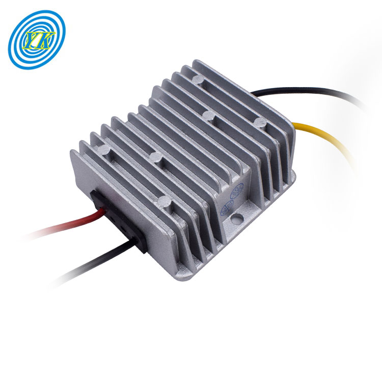
Voltage regulation in isolated power systems is a critical aspect of ensuring stable and reliable power delivery to various electronic devices and systems. This article will discuss several techniques used to maintain a consistent output voltage despite variations in the input voltage or load conditions.
1. Understanding the Minimum Controllable On-Time for High-Frequency Switching: When designing isolated power systems that operate at high switching frequencies, it is essential to consider the minimum controllable on-time of the power controller. The on-time, or the duration the power switch is conducting, can become a limiting factor when the input to output voltage ratio is very small. To address this, designers can either reduce the switching frequency or employ controllers designed to handle lower duty cycles.
2. Utilizing External References for Low Output Voltage Regulation: In cases where the output voltage is significantly lower than the reference voltage of the controller, an external reference can be employed. By connecting an external reference with a higher voltage than the controller's internal reference to the feedback loop, the system can regulate to voltages below the internal reference. Choosing an accurate reference can significantly improve the precision of the output voltage.
3. Biasing Techniques to Achieve Desired Voltage Outputs: Integrating an external reference requires a resistor to provide the necessary bias current. This setup allows the controller to 'trick' the system into regulating at voltages lower than its internal reference. This approach is beneficial when dealing with very low output voltages that are challenging to achieve with standard controllers.
4. Addressing Accuracy Concerns in Voltage Regulation: The accuracy of the output voltage can be affected by the choice of the external reference. For applications where precision is paramount, it may be necessary to use a reference with 0.1% accuracy, although this may come at a higher cost compared to the more common 1% or 2% references. Some controllers offer auxiliary bias rails that might serve as an alternative to the external reference; however, these rails are usually less regulated and might not provide the desired accuracy.
5. Selecting the Right Controller for Low-Voltage Applications: When the requirement is to regulate a very low output voltage, the selection of the controller becomes crucial. While controllers with a reference voltage lower than the required output voltage are rare, especially below 0.8V, certain techniques and additional components can be utilized to overcome these limitations and achieve the necessary regulation.
In summary, this article explores the intricacies of voltage regulation in isolated power systems, particularly focusing on methods to manage low output voltages and the importance of choosing the correct components and techniques to maintain accurate and stable voltage levels.
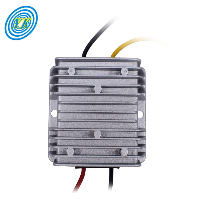
Electromagnetic interference (EMI) can significantly impact the performance and reliability of DC-DC converters in industrial applications. Implementing effective EMI filtering strategies is crucial for ensuring that these power conversion devices operate without disrupting or being affected by unwanted electrical noise. Here are some strategies for minimizing EMI in industrial DC-DC converter applications:
Local Shielding of Converters: It's important to design PCBs with the possibility of adding local shields to mitigate EMI. Even with magnetically shielded inductors and good PCB design, EMI can still be a concern. One method is to incorporate "fencing solder strips" on the PCB, which can connect to the ground reference plane (GRP) and provide a means to add shields if necessary
Strategic Placement of Components: Keeping antennas and coaxial cables at a distance from DC-DC converter circuitry can reduce the risk of EMI coupling. Since converters can generate high electric fields, they can potentially interfere with nearby receiver equipment, affecting the performance of wireless communication modules.
PCB Stack-up and Grounding: A well-thought-out PCB stack-up is essential. Signal layers should have an adjacent GRP to prevent noise and signal coupling. Power traces should also follow this rule to reduce radiated EMI and crosstalk. A solid GRP is crucial as gaps or slots can propagate EMI across the board
Use of Shielded Inductors: Opting for shielded inductors instead of unshielded ones can confine magnetic fields more effectively. Shielded inductors prevent the spread of the H-field, which is critical in minimizing EMI
Proper Orientation of Inductors: The orientation of inductors can influence EMI characteristics. Inductors have a start and an end to their windings. By connecting the start of the winding to the switched output of the converter IC, and the end to the output filter, EMI can be reduced since the start is somewhat shielded by the subsequent turns
Concentrated Converter Circuitry: Keeping all converter circuitry on the top layer of the PCB and not running fast switching signals through multiple layers can prevent EMI issues. Also, keeping converter components close to the IC can minimize the loop areas, which is crucial for reducing EMI
These strategies are derived from a combination of best practices in PCB design and specific techniques for mitigating EMI in DC-DC converters. By carefully designing the converter's physical layout and incorporating EMI-reducing components, industrial applications can achieve better performance and compliance with EMC standards.
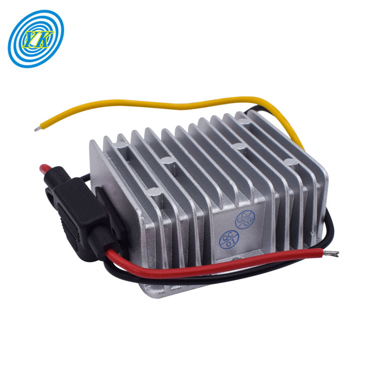
The field of military electronics is one that demands the utmost in reliability and performance, especially when it comes to power conversion technologies. High voltage DC-DC converters are a crucial component in this domain, as they provide the necessary power conversion capabilities for a wide range of defense-related applications.
In recent developments, Gaïa Converter has introduced the MGDM-500 series, a 500-Watt DC-DC converter designed specifically for high-reliability aerospace and defense applications. This series represents a significant innovation in the power supply domain, offering engineers the flexibility to create power architectures that adhere to stringent military standards, such as MIL-STD-461/704/1275 and DO-160.
The MGDM-500 series stands out for its ability to deliver a stable 500-Watt power output across a wide input voltage range, from 9 to 36 volts DC, with the capacity to handle transient input voltages up to 40 volts DC for brief periods of time. This robustness is complemented by high power density and efficiency, packaged in a compact half-brick format.
Notably, the MGDM-500 series features galvanic isolation of 1,500 volts DC, which is critical for ensuring the safety and reliability of electrical systems by preventing ground loop issues and providing protection against voltage spikes. Additionally, the output voltage of these converters can be adjusted from 90 to 110 percent, allowing for greater control and customization to meet specific application requirements.
Perhaps one of the most impressive aspects of the MGDM-500 series is its ability to operate without derating over a wide temperature range, from -40 to 105 degrees Celsius. This ensures that the converters can reliably function in the extreme environmental conditions often encountered in military settings.
In summary, innovations like the MGDM-500 series from Gaïa Converter are pushing the boundaries of what's possible in high voltage DC-DC conversion for military use, offering high reliability, adaptable power output, and operation under extreme conditions. These advancements are critical for powering the next generation of military technology, where failure is not an option.