News
From Design to Verification: A Comprehensive Guide to Building and Testing an Adjustable DC Power Supply
Click: 908 Date: 01/25/2024 3::45::40 PM
From Design to Verification: A Comprehensive Guide to Building and Testing an Adjustable DC Power Supply
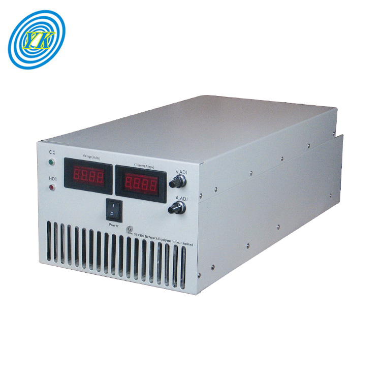
This section delves into the foundational elements of constructing an adjustable DC power supply. It begins with understanding the prerequisites and strategically planning the project. This includes identifying the specific requirements for the power supply, such as the desired output voltage range and current capacity, and selecting suitable components accordingly.
The construction of the power supply starts with the AC plug, which forms the entry point for the power supply. Following this, a step-down transformer is required to convert the AC mains voltage to a lower level that can be controlled by the power supply. The transformer's role is to reduce the high AC voltage from the mains line to a lower level, as the power supply will provide a variable DC voltage within a specific range.
Next comes the full-wave rectifier, which takes the AC voltage from the transformer and converts it into a DC voltage. This is crucial as the rest of the circuit operates on DC power.
The core of the power supply is the regulator, which controls the output voltage. This is achieved by adjusting the resistance of a resistor and a potentiometer in conjunction with the regulator. The output voltage is determined by the formula VOUT = 1.25V * (1 + R2/R1), where R1 and R2 are the resistances of the potentiometer and the resistor respectively. By altering these resistances, the output voltage can be varied within the desired range.
Finally, a heat sink is attached to the voltage regulator to dissipate excess heat generated during operation. This is essential as the regulator operates by converting input voltage into output voltage based on the values of the resistor and the potentiometer. When the potentiometer's resistance is at its maximum, it does not generate much heat. However, if the potentiometer's resistance is near zero, the regulator outputs a low voltage, resulting in a significant voltage difference and consequently, a large amount of heat. Hence, the heat sink is vital to prevent potential damage to the circuitry of the power supply.
In conclusion, designing an adjustable DC power supply requires careful planning and selection of components, understanding of basic electronics principles, and meticulous attention to detail in assembling the circuit.
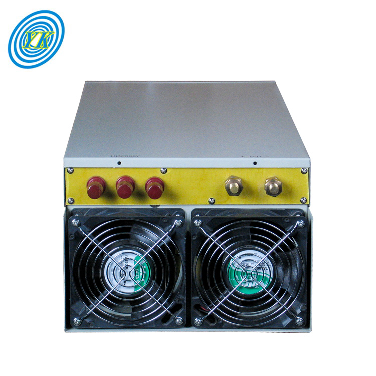
In the realm of designing an Adjustable DC Power Supply, the selection and placement of components play a crucial role. Here are some key points to consider:
Choosing the Right Regulator for the Power Supply
The first step involves selecting the right regulator for the power supply. There are two primary types of regulators to choose from: linear regulators and switched-mode regulators. Linear regulators provide low noise output but have higher heat dissipation, requiring cooling systems. On the other hand, switched-mode regulators are highly efficient over a broad current range but can generate switching noise, causing spikes in response.
Thermal Management for Power Supply
The performance of a power supply is directly dependent on heat dissipation. Most electronic components emit heat when current passes through them. The amount of heat emitted depends on the component's power level, characteristics, and impedance. Therefore, choosing a suitable regulator can reduce heat dissipation in a circuit. If a linear regulator is chosen, a heat sink or other cooling methods are recommended if the system allows it.
Decoupling Capacitor and Bypass Capacitor
When power is distributed across the board, different active components can cause ground bounce and ringing in a power rail, leading to voltage drops near the power pins of components. To counteract this, decoupling and bypass capacitors are used near the power pins of components to provide for short spikes in the current requirement of the device. Decoupling capacitors act as a secondary power source, providing the current needed by the IC, and act as a local source of charge to support a switching event. Bypass capacitors bypass the noise and reduce fluctuation in the power bus.
Remember, the placement of these components in the circuit is equally important. The decoupling capacitors have to connect close to the power pins of the IC and the other end directly to a low impedance ground plane. Short traces to the decoupling capacitors and ground vias are required to minimize additional inductance in series for this connection.
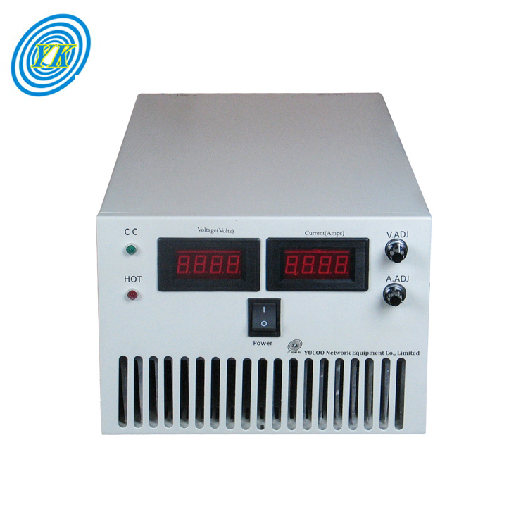
This section discusses the various strategies employed to confirm the functionality of a power supply, such as utilizing Pulse Width Modulation (PWM) and Pulse Frequency Modulation (PFM).
Pulse Width Modulation (PWM) is a method used to control the power supplied to electronic devices. It involves varying the duty cycle of a square wave signal to produce a variable average voltage. When measuring the efficiency of DC-DC converters, it's crucial that the voltage and current meters are sensing their values at the proper locations. For instance, a setup can be used to perform efficiency measurements of a boost converter operating in PWM mode. It's important that the voltage displayed on the power supply is not used in efficiency calculations. Instead, a separate voltmeter should be connected directly across the input of the converter. This ensures that the measured voltage is the true voltage at the input of the converter and does not include additional voltage drops across the current meter or any cabling.
Pulse Frequency Modulation (PFM), on the other hand, is another technique used to measure the efficiency of power supplies. When performing measurements on DC-DC converters using PFM, proper care must be taken to ensure that the measurements are accurate. An accurate PFM mode efficiency measurement is critical for systems which require high efficiency at low loads, such as smart home systems, tablets, wearables, and metering. The test setup required to obtain correct measurements differs from the test setup that is normally used to acquire measurements of the device operating in PWM mode. An improper test setup can result in incorrect efficiency measurement data that varies considerably from the data sheet specifications.
In conclusion, both PWM and PFM are essential tools for verifying the performance of power supplies. By carefully applying these techniques, engineers can ensure that their power supplies are functioning as expected and meeting the necessary performance criteria.
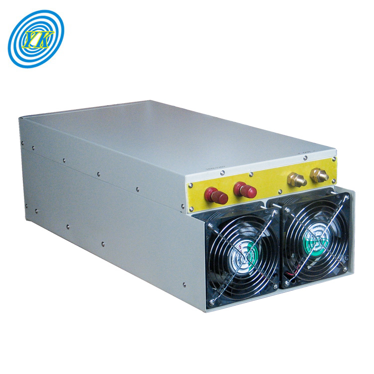
This section delves into the various power management techniques utilized in Direct Current (DC) power supplies, with a focus on the application of MAX1742 and MAX8686.
Power management techniques are crucial in DC power supplies as they dictate the efficiency and performance of the power supply. Efficiency, a key parameter, is especially important for devices operating from a battery, such as laptop computers and small handheld equipment. For instance, a DC-DC converter supplying 50W at 85% efficiency still dissipates 8.8W of heat inside the case.
Two fundamental power supply configurations used with DC power management subsystems are linear and switch-mode power supplies. Linear power supplies always conduct current, while switch-mode supplies convert DC to a switched signal that is then rectified to produce a DC output. The differences between these two configurations include size and weight, power-handling capability, Electromagnetic Interference (EMI), and regulation.
One of the commonly used techniques in switch-mode power supplies is Pulse Width Modulation (PWM). PWM is used to control the power-switch output voltage. The ratio of on time to the switching period time is the duty cycle. The higher the duty cycle, the higher the power output from the power semiconductor switch.
Another technique is the use of voltage regulator ICs. These ICs obtain a DC input from rectified AC or a battery. In operation, the voltage regulator feeds back a percentage of its output voltage that is compared with a stable reference voltage. If the output voltage tends to rise or fall compared with the reference, the feedback causes the output to remain the same.
MAX1742 and MAX8686 are examples of such voltage regulator ICs. They play a crucial role in managing the power supply in DC power supplies.
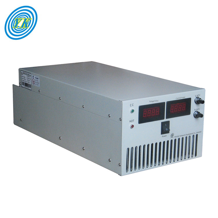
In the final section, we explore the application of theoretical principles in real-world scenarios, offering insights into the practical use of semiconductor devices within power supplies. This involves understanding the structures, symbols, and operations of power semiconductor devices, as well as their characteristics, and how these elements contribute to the functioning of power supplies. We also examine the different types of power semiconductor devices, such as power diodes, power MOSFETs, IGBTs, thyristors, and SCRs, and their specific roles in power supply systems. By applying these theoretical concepts, we can better understand how these devices work together to create efficient and reliable power supplies.