News
Comprehensive Guide to Switching Power Supply: From Basic Understanding to Design Techniques, with a Special Focus on Yucoo’s Switch Power Supply
Click: 798 Date: 12/18/2023 10::00::30 AM
Comprehensive Guide to Switching Power Supply: From Basic Understanding to Design Techniques, with a Special Focus on Yucoo's Switch Power Supply
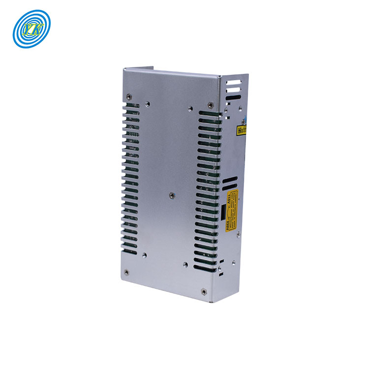
Understanding the Basics of Switching Power Supply
Switching Power Supplies (SMPS) are a prevalent and sometimes necessary choice for DC-DC power conversion. These circuits offer distinct advantages and tradeoffs when compared to other methods of converting DC power. This article will present an easy-to-understand overview of the basics of Switching Power Supplies.
Why Switching Power Supplies?
Most electronic DC loads are powered from standard power sources. However, the voltages these sources provide may not align with the levels required by various devices like microprocessors, motors, or LEDs, especially when the source voltage is unregulated. For instance, the voltage of a standard Li+ cell or NiMH stack could be either too high or low, or drop too far during discharge to be used in conventional applications.
Versatility and Customization
Switching Power Supplies offer a solution to the problem of converting a standard source voltage into a usable, specified output voltage. There are numerous SMPS topologies to step up, step down, invert, or even step up and down the input voltage. This versatility makes SMPSs attractive as a topology can be selected to fit nearly any output voltage.
Modern SMPS ICs are designed with varying levels of integration, enabling engineers to choose among topologies with more or fewer of the standard SMPS features brought into the IC. This flexibility eases the design burden for commonly used, application-specific power supplies or offers engineers basic SMPS ICs for custom projects.
Efficiency
Efficiency is a common concern when converting DC power. For instance, stepping down an input voltage to achieve a lower output voltage often requires an efficient solution. A simple solution would be to implement a linear regulator, but this method can become inefficient, especially if the voltage differential is large.
A well-designed SMPS can achieve 90% efficiency or more, depending on the load and voltage levels. This high efficiency is the primary advantage of SMPS designs and leads to other benefits, such as a reduced thermal footprint and increased component lifetime due to improved reliability.
Disadvantages and Tradeoffs of SMPSs
Despite their high efficiency, SMPSs do have drawbacks. The most often cited issue regarding switch-mode converters is their tendency to radiate electromagnetic interference (EMI) and conduct noise. Fortunately, good component placement and PCB layout techniques can successfully combat EMI and reduce noise.
SMPSs can also be complex and require additional external components, which can increase the overall cost of the power supply. However, most SMPS IC manufacturers provide detailed literature about device operation and choosing correct external components, which can help manage these issues.
In conclusion, despite some challenges, SMPSs are widely used due to the efficiency and versatility they offer. They are a necessary component in many applications and often required for achieving highly efficient, reliable DC-DC power-conversion systems.
Design Principles and Techniques of Switch Mode Power Supply
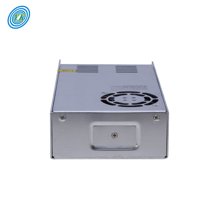
Switch mode power supplies (SMPS) are a fundamental component in many electronic devices due to their efficiency in converting power. They operate by switching the input current on and off rapidly to stabilize the output voltage. This article will delve into the design principles and techniques of SMPS.
1. Understanding SMPS
Switch mode power supplies operate differently from linear power supplies. While linear power supplies operate continuously, SMPS switch on and off rapidly, controlling the transferred energy by varying the duty cycle, the proportion of time the switch is on versus off. This method improves efficiency, reduces size and weight, and allows for a wide input voltage range.
2. Basic Design Principles
The design of a SMPS is guided by several principles. First, the choice of the topology is crucial and depends on the application requirements. Common topologies include flyback, forward, buck, and boost converters. Each has its advantages and trade-offs in terms of complexity, efficiency, cost, and performance. Second, the design must ensure stability throughout the operating range. This involves careful selection and placement of components such as inductors and capacitors. Third, the design must consider the control strategy, such as pulse width modulation (PWM) or resonant mode control, which affects the performance and complexity of the power supply.
3. Techniques for Improving Performance
Several techniques can improve the performance of a SMPS. For example, synchronous rectification can enhance efficiency by replacing diodes with controlled switches, reducing power losses. Furthermore, soft-switching techniques can minimize switching losses and electromagnetic interference (EMI). Additionally, digital control methods can provide flexibility, precision, and advanced features, such as fault protection and communication capabilities.
4. Design Considerations
Designing a SMPS involves many considerations. For instance, the power supply layout should minimize parasitic elements and EMI. The selection of components should consider factors like efficiency, cost, size, and thermal management. Safety standards and regulations, such as those related to EMI and efficiency, must also be taken into account.
5. Case Study: High-Efficiency SMPS Design with Advanced Features
An example of a high-efficiency SMPS design is the use of gallium nitride (GaN) devices, which can operate at higher frequencies and temperatures than traditional silicon devices, allowing for smaller, more efficient power supplies. Advanced features such as digital control and communication (PMBus) can also be incorporated to provide precise control, fault protection, and system-level power management.
In conclusion, the design of switch mode power supplies involves a blend of principles, techniques, and practical considerations. The goal is to create a power supply that meets the application requirements in the most efficient, reliable, and cost-effective manner.
Exploring Power Supply Switching in Multi-Source Systems
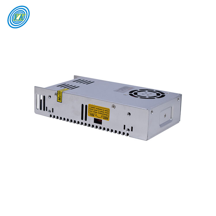
The operation of modern power systems depends heavily on the reliability and efficiency of power supply systems. In multi-source systems, the process of power supply switching plays a crucial role in maintaining consistent and safe power delivery. This article explores the concept of power supply switching in multi-source systems, focusing on strategies to manage voltage sags, control active and reactive currents, and ensure safe operation.
Voltage sags in power systems can lead to significant issues, such as the disconnection of distributed generation and failure of electrical equipment. One of the cutting-edge solutions to this problem is the use of a flexible multi-state switch (FMSS). This novel type of power electronic equipment is capable of supporting the voltage during grid faults, providing a stable power supply even in challenging conditions.
A critical aspect of power supply switching in multi-source systems is the control of active and reactive currents. A positive-negative-sequence compensation (PNSC) scheme can be utilized to manage these currents effectively. By eliminating active power oscillations at the port of voltage sags and reducing coupling oscillations of other ports, the PNSC scheme ensures the smooth operation of the power supply system.
To support the voltage in a distribution network, a voltage control strategy can be proposed by introducing a three-port FMSS. This approach is based on the characteristics of the voltage support under the PNSC scheme, and it involves two main strategies. First, a proportional-integral controller can be introduced to provide the reactive power references, which eliminates the errors when estimating the grid voltage and impedance. Second, a current limiting scheme can be adopted to keep the port current in a safe range by adjusting the active and reactive power references.
The successful implementation of these strategies can significantly enhance the performance of power supply switching in multi-source systems. Simulations of the voltage support strategies in two different voltage sags demonstrate the feasibility and effectiveness of the proposed control strategies. These results provide valuable insights for the design and operation of power supply systems in various applications, from industrial facilities to residential buildings.
In conclusion, power supply switching in multi-source systems is a complex but critical process. By using advanced control strategies and power electronic equipment, it is possible to overcome the challenges associated with voltage sags and current control, ensuring the reliable and efficient operation of the power supply system. As the demand for electricity continues to grow, the importance of optimizing power supply switching in multi-source systems will only increase.
The Role of PWM Control Circuit in Switching Power Supply
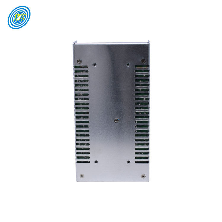
The Pulse Width Modulation (PWM) control circuit plays a pivotal role in the operation of a switching power supply. It essentially controls the on and off states of the power switches, which are integral components of the power supply. This control mechanism is vital for the efficient regulation of output voltage and the overall performance of the power supply.
The PWM control circuit operates by generating a series of pulses. The width of these pulses (hence the term "pulse width modulation") can be adjusted according to the power supply's requirements. This width is directly correlated to the amount of energy transferred to the output of the power supply. A wider pulse means more energy is transferred, resulting in a higher output voltage, and vice versa.
In a switching power supply, the PWM control circuit interacts with other components such as the power switches, the input voltage source, and the load. When the input voltage and load conditions change, the PWM control circuit adjusts the pulse width accordingly to maintain a stable output voltage. This is done by comparing the actual output voltage with a reference voltage, and adjusting the pulse width to minimize the difference between the two.
A key advantage of using a PWM control circuit in a switching power supply is its high efficiency. Since the power switches are either fully on or fully off, they do not operate in their linear region, which would result in higher power losses. Moreover, by precisely controlling the energy transfer, the PWM control circuit can ensure that the power supply operates at its optimal point, further improving its efficiency.
Furthermore, PWM control circuits can also provide additional functions such as over-voltage protection, under-voltage protection, and over-current protection. These features enhance the reliability and safety of the power supply.
In conclusion, the PWM control circuit is a crucial part of a switching power supply. It is responsible for regulating the output voltage, improving the efficiency, and ensuring the safe operation of the power supply. As technology advances, PWM control circuits will continue to evolve, offering even better performance and additional features for switching power supplies.
Improving Electromagnetic Compatibility in Yucoo Switch Power Supply
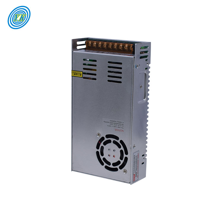
In the modern world, switch power supplies are a crucial component of many electronic devices. They convert electrical power efficiently and effectively, but one of the challenges they present is electromagnetic interference (EMI). This article will focus on improving electromagnetic compatibility (EMC) in Yucoo switch power supplies.
EMI has long been a concern with switching power supplies. Their high-frequency switching of voltage and current generate higher order harmonics that have the potential to cause interference with system operation. To mitigate this issue, optimal solutions must come from techniques applied during the design process.
One of the significant causes of EMI in power supplies is the rapidly changing currents and voltages, which generate electronic noise. This noise may be induced by coupling between circuit elements through the action of either a magnetic or an electric field.
In the case of Yucoo switch power supplies, several strategies can be employed to improve EMC. Firstly, careful attention should be paid to the design and layout of the circuitry. Minimizing current loops and containing magnetic fields is a proactive way of reducing EMI at its source. This can be achieved by designing transformers for switch mode usage that minimize leakage inductance between primary and secondary windings.
Another strategy involves the use of shielding. Shields of non-magnetic, conductive material can be used for magnetic fields. The process involves the magnetic noise inducing eddy currents to flow in the enclosure, which in turn generate a canceling magnetic field.
The use of filters is another effective way of reducing EMI. Filters can be designed to provide current attenuation between the power supply and the power source, reducing both differential mode (DM) and common mode (CM) noise.
Lastly, the use of flux straps or "belly bands" around transformers can help reduce stray magnetic fields. These copper bands provide a path for the eddy currents that result from the leakage inductance magnetic dipole, creating an opposing magnetic field that cancels the original field at close proximity to the transformer.
In conclusion, improving EMC in Yucoo switch power supplies involves a combination of careful circuit design, effective shielding, the use of filters, and the application of flux straps. By implementing these strategies, the performance of Yucoo switch power supplies can be significantly improved, minimizing the potential for EMI and ensuring efficient and effective operation.